Barry Mishkind

The Broadcasters' Desktop Resource

GatesAir

Solutions & Tech Tips

Death by Capacitor

Things happen as equipment ages, especially after it has been in service for over ten years. Keeping older broadcast gear going past its support life, as determined by the manufacturer, sometimes takes older gear right to the edge – or right over the edge. My war story is called “Death by Capacitor.”

It was an unusual case that made our DX-50 act a little weird, the evening our BE C-Quam AM Stereo generator went nuts.

The symptom was that the Day/Night equalizer switching had become erratic. When the C-Quam was switched back on with the main transmitter at about 7:30 PM, the transmitter started going into overloads, dropping off the air.

Troubleshooting Time

As I worked through the transmitter, I discovered the problem. The stereo generator Day/Night settings were both on, and the switching was going from erratic to working to not working. Actually, we do not need any of the equalization changes that the exciter could provide but the switching relay pushes the signal in and out of that board.

The funny part is that the transmitter design offered no panel light indication that the PLL was not locked, except to show that the “mute” was activated. As I worked the Day/Night switch it got worse, becoming very erratic. It was going crazy as the switch was trying to make both modes go.

Diagnosis

As it turns out none of those Day/Night adjustments are even used in this installation. It was a carryover from the days of transmitters with iron. However the audio signals go into and out of Day/Night board. Once that relay went erratic, sending two sets of signals to the modulator, it was troubling to the transmitter.

As I worked through the circuit, the operation of the switch’s flip-flop was stable. However, it turned out the parts after the flip-flop were not. As I looked at parts I suspected high value resistors such as two 1-meg ohm resistors, various diodes in the circuit, and some PNP transistors. Each of the many parts were measured and almost all looked good, reading on the DVM just as marked. The only clue was some goo by the IC socket.

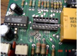
Finally, checking the 100 uF capacitor, I found it measuring only 74 uF. A closer inspection showed the capacitor had spilled its contents and eaten away a trace on PC board.

This trace was connected to the mute signal to stop Day/Night adjust switch selection. In fact, the trace was eaten completely open! This is a case were the capacitor’s chemical leakage actually ate away the foil path. Failure was from the chemical action; the picture shows the damage.

I have only seen this happen one other time. This particular unit is a BE brand AM stereo generator and is above average in construction. It is now probably about 19 years old; it really was made to last.

Repair

Solving the problem entailed cleaning the pc board and replaced the missing trace for mute disable. It appears the 2004 IC was damaged, but the affect is to status LED and did not affect the relay switch.

It was an interesting case indeed, really taxing the skill-set in diagnosing a simple flip-flop circuit.

The lesson learned is electrolytic capacitors need to be changed out after ten service years – and must be done at 15 years even if the gear still appears to be working. The danger is not just the loss of component value but the goo oozing out from bad capacitors. For this unit it is clearly time to blitz all the capacitors

– – –

Warren Shulz is the Chief Engineer for WLS in Chicago. Contact him at warren.shulz@citcomm.com

Continue reading

Replacing Hard-to-Fit Electrolytics in Video Monitors (…or anywhere)

We had an off-brand flat-screen monitor in our station that quit working after blowing five electrolytics. After inspection of the motherboard, it was clear the manufacturer did not use ones that were of low enough impedance – so I ordered some replacements that were of the appropriate value.

Unfortunately two of the capacitors were too tall to fit under the cover, as there was no room on the board to lay them down. Unwilling to just give up and buy a new monitor, I took a unibit and punched holes in the chassis to allow room for the tops of the cans.

All too often a replacement part will not fit perfectly. A well-placed hole in the case solves the problem.

As is common with most all consumer electronics, space is always at a premium. So, even with the holes made in the motherboard case, there still was the problem of fitting the electrolytics inside the plastic back of the monitor itself.

Another set of carefully placed holes in the back of the monitor provided the way to solve the problem completely.

Another set of holes, and it all fits together.

As shown in the picture, everything fit back together quite nicely – and the monitor was working well once again.

It all goes to show that just because some parts initially may not seem to fit, repairs are still possible – saving the gear and money.

– – –

Scott Todd is the Chief Engineer for KKMS in Richfield/Eagan, MN. Contact Scott at stodd@kkms.com

Continue reading

Adjusting a Harris 30 Amp Motor-Driven Contactor

Here is an adjustment procedure for Harris motorized (not solenoid operated) AM RF contactors. From time to time there are reports about these operating erratically and unreliably, so the material was sent to be posted here.

This contactor in question is the Harris 30 Ampere motor-driven contactor. The part number of the contactor is: Harris Model HS-4P 994-8524-001

Adjustment Procedure

  1. Remove the contactor from the unit.
  2. Using a table or other suitable surface, lay the contactor in an inverted position on the contacts. From this position it is possible to observe the micro-switches and the adjustable brackets that contact the micro-switches.
  3. Depress the manual override, (located on the contactor, on the opposite side from the terminal board), move the center contact arm either direction, to its fullest travel.
  4. Observe the clearance between the micro-switch and the adjustable bracket (it will be necessary to lightly depress the switch arm, being careful not to bend the arm). The bracket has two separate steps; the step with the least amount of clearance will be the one to check.
    With the slide arm set at its fullest travel, the clearance between the bracket and the micro-switch roller should measure between 0.0 – l/16″ If the clearance is greater than this, the two screws that hold the adjustable bracket in place should be loosened and the bracket adjusted accordingly.
  5. After initial adjustment, the contactor should be cycled a few times and then the clearances rechecked, this operation can be done by hand if control voltages are unavailable.
  6. Once the clearance has been established, move the center contact arm to the other side and repeat steps 3 thru 5.
  7. When clearances are satisfied for both sides, check switch operation by manually moving the switch and verifying opens and closures using an Ohm meter, test light or other suitable device.
  8. Reinstall contactor.

Continue reading

Sine Systems RFC-1/B Remote Control Bug

You should check the date on your RFC-1/B.

A bug has been discovered in the hardware, which can cause the calendar to roll over to the wrong year. Some report on that on January 1st it rolled back to 2000. Other reports have seen some other dates.

SHORT STORY: Sine Systems says to just go ahead and reset the date – and relax, everything will be OK.

Longer story and explanation: The issue is mostly of concern to those people using the remote control to change power/pattern, or initiate some other action. According to Sine Systems, the problem is caused by two routines that can, under unpredictable conditions, “step” on each other, and output the wrong year. (Each routine apparently tries to utilize the same tiny piece of scratch memory in the unit, and sometimes – but not always – causes the rollover problem.)

Since the Sine RFC-1/B is only using the calendar to calculate leap years, it does not matter if the unit thinks it is 2010 or 1910. Once you reset the year, everything is fine, all the way to the year 2100.

Sine says this will be fixed in the upcoming V6 software, although no date has been set for its release. In the meantime, if a user is really bugged about this minor issue, Sine will provide an update chip – but they warn that this will reprogram the RFC-1/B back to factory defaults, and is probably cause more work than just changing the year and moving on.

Continue reading
AAT