

The Dangers of Leaving “Well Enough” Alone
[August 2009] Contrary to bean counter logic, solid state does not mean “no maintenance required.” Stations that want reliable service, even from some of the best-designed gear need to pay attention to continual, regular maintenance – from air filters to electrolytics. Warren Shulz is one who strongly believes in trying to stay ahead of potential component deterioration. Nevertheless, from time to time, a surprise happens. Warren takes it as a learning experience.
As many of you know, we have run a Harris DX-50 for nearly a dozen years. By implementing a good program of preventive maintenance, with extensive documentation (the maintenance history file, on the transmitter site computer, now holds over 5 MB of text), we have effectively minimized downtime – our auxiliary transmitter is used more by choice, not due to failure of the main.
Of course, no matter what you do, Murphy just has to stop buy once in a while and teach you something new about the equipment under your care. And, to be sure, while this tip is focused on the DX-50, the principle applies to whatever unit is in service at your site.
Down In Drive Time
Early one Sunday morning the WLS-AM DX-50 dropped its carrier – with the system switching to the backup transmitter without event. We quickly connected via remote control but were unable to restart the DX-50 – nor reset a low voltage supply failure. It was time to visit the transmitter site.
Upon arrival one of the first things I noted was the B+ Fault display LED was on – and it would clear.
Troubleshooting
Checking the various meter readings, I found that the DC regulator for the B-side Mod encoder – nominally +5 VDC – was at just 4.29 VDC both on the previous Friday and earlier on the day of failure. This is a regulated output from Mod B encoder and the alarm is a cross-check, activating an interlock.
One of my first thoughts was that it was odd for this reading to shift despite a two-year history of reading 4.69 VDC time after time.
Following the circuit path, I moved connector J6 (on the DC regulator) and the B side voltage quickly changed back to a normal reading, stabilizing at 4.72 VDC.
As a double check, the A side read 4.78 VDC (internal DVM). With an external DVM the reading was 4.61 VDC at both the Mod-encoder test point and the test point on the regulator board (TP-16 is the 3.0 Volt shutdown reference).
Diagnosis and Fix
It seemed apparent that the issue was related to the connector, although these tin plate connectors have large surfaces and you would never think of them being erratic. Good contact is important: these bias voltage-level tests are critical shutdown points if the FET power PA amplifier bias is not correct. Their purpose is to protect the 1,024 FET devices from failure – as in all of them could be destroyed! – because of a bias fault.
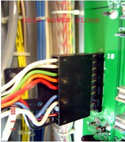
The plug would have benefitted from
a bit of exercise over the years
The repair process was simple. I cleaned all the tin plate connectors in the front of the PA modules, wiping them with gold wipe chemical cloth, and then treating them with DeoxIT D100L by Caig – a contact lubricant and preserver. Afterward, it was clear that the connectors moved on-off with less friction than before. (Other ribbon connectors in the DX-50 are gold on gold and would be more stable.)
Basically, I suspect the connection became erratic over time and the comparator simply switched off. This was a good find and should be a warning that connectors that have not been moved for years can become a source of intermittent faults. I would suggest making it a part of the yearly maintenance plan.
– – –
Warren Shulz is the Chief Engineer for WLS in Chicago. Contact him at warren.shulz@citcomm.com