

Don’t Do That: Slugs Should Be Left In The Garden

If you are in the Broadcast Engineering business as an employee or contracting member of the Gainfully Self-Unemployed, you are probably over the age of majority and are not too crazy about folks shaking their finger at you bellowing, “Don’t Do That!”
Get over it.
Actually, quite often, those well-meaning folks are either trying to save you from killing yourself, your apprentice, or the station cat. Other warnings are to prevent unnecessary work or actions that will not solve a problem. Despite well-meaning insubordination, you ought to listen to what they have to say and not just write it off as their childish folly. Those older, and some younger, may have seen a few things you might have missed.
SLUGS
The word ‘Slug” has about 40 various synonyms and related words in both the Noun and Verb.
To many who are broadcast technically inclined, this seemingly indestructible ceramic material can possibly be mistaken for the slimy crawling things in your garden.
OK, this may not be very kind to say that the invention of the art of “Slugging” is not helpful because in certain environs is has a use, but this use is definitive and is to say the least, Narrow Minded.
THE CLAIM
You can replace a Slug with at Tuner but you cannot replace a Tuner with a Slug. This is a harsh statement but it contains a most revolutionary truth that impedance matching can know.
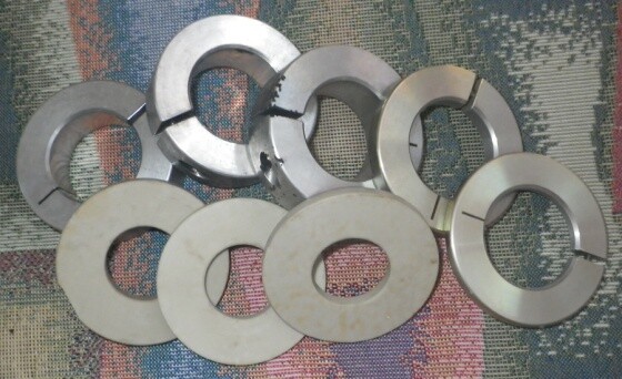
In deference to the positive aspects of “Slugging,” when you “Slug” a line, elbow or other component of the RF transmission system to accomplish a change in the presented tuning or impedance, you insert what looks like pale yellow ceramic Krispy Kreme into the line. The more correct term for this doughnut is the trade name Steatite. This product is manufactured by a number of companies throughout the world and is considered a ceramic but it has some very specific qualities.
Without getting in to the mathematics which few people really understand, when you insert this coaxial lump of ceramic into the transmission system, you introduce a predictable amount of inductance and capacitance into the system in an attempt to shift, compensate for, or match one impedance to another.
USE IT HERE
In keeping to the positive thoughts for yet another moment, there are certain narrowband applications for slugs that are just the ticket for this art.
The most applicable use is elbows, gas barriers, and an all metal, shorted dummy load commonly used for television transmitter reject loads. Since this device is predominantly tuned by the physical construction of the length of the center conductor to a shorting plate, along with the diameter of the internal coaxial ratio to the housing, the Slug only shifts the center tuning a tad – and thusly the symmetry of the load is achieved.
This result is also dependant on the dielectric constant of the type of coolant you use.
Of course, all coolants are not created equally in RF service. This frequency sensitive short is center-tuned with a precision slug (which in this case happens to be metallic) and is virtually indestructible as long as the cooling fluid is circulating.
Beyond this load, the positive uses for the lowly Slug diminish fast.
SMALL PART, BIG EFFECT
The slug by its nature is relatively small in size and volume compared to the very high dielectric affect that it has on a transmission line.
The relative elephant inserted into the line is regulated in effect by the longitudinal thickness of the slug and rarely by the diameter (unless it is a machined metal slug). This highly potent lump of inductance and capacitance causes a dramatic effect on the impedance transformation of the real load toward the desired line impedance, regardless of the impedances.
This touches on the need to note that slugging is a tool that is able to be used at both 50 Ohm, and 75 Ohm coaxial line systems as well as open waveguide.
While it is the machined metallic slug that has the most moderation of control by the grace that it is able to be both positioned in the line or waveguide and the size (volume) of the slug can be readily changed. This is the most versatile of the choices but metallic slugs are not as commonly found, except in waveguide.
THE PROBLEM
The real problem rears its ugly head when the insertion of a single slug in to a coaxial system cannot effectively make the impedance transformation due to the fact that the slug is typically only placed in one linear spot in the line, where its size (reactance) is selected for the appropriate result.
This is where the Narrow Minded nature comes in to play. We must remember that we are not actually tuning the antenna.
What we are doing is matching a coat hanger to the desired impedance of the transmission line. In my experience, the application of a single slug may foster an impedance match but is less than 50 percent effective at achieving the best or ideal tuning solution for an antenna (matching solution).
A BETTER SOLUTION
If compared to the use of a genuine physical multi-ported tuning device, the slug may achieve a reasonable or even barely useful solution – but only an actual tuner device will achieve the best solution in every case.
I know, I know, these are fighting words but the best is yet to come.
In antenna tuning, the actual tuning of an antenna can only be accomplished by physically altering the geometry or size of the antenna. Facts be facts – adding gizmos, capacitors, or slugs to anything that is not actually a part of the elements of the antenna, surrounding parasitics or ground plane, is not truly developing a tuned antenna.
THE COMBATANTS
A tuned antenna is an antenna that will exhibit the correct complex impedance (and low resulting Return Loss) when derived from a resistance and reactance that is presented when the raw antenna is mounted in its final living environ, and which is really the correct impedance.
We will use 50 Ohms for these further discussions.
WHY A TUNER
If the complex impedance of your new antler after being installed in its final resting place is a whoppingly awful number and the slugged solution cannot achieve depth and symmetry at the same time, you may want to consider that you really need a tuner.
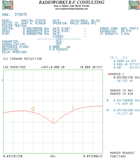
Figure 1 shows an antenna system that was installed and slug tuned.
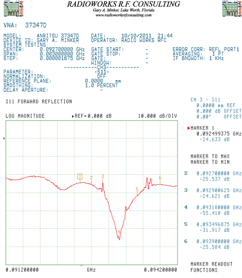
As you look at the graph, it is easy to see that there are some serious issues here. In order to make the numbers more manageable for many people, we will use Return Loss in Log Mag –dBm. (These images are embedded at high resolution and can be copied and pasted for enhanced viewing. 92.7 MHz is the desired center frequency.)
Figure 2 reveals that the raw antenna with the slug removed is quite a different result.
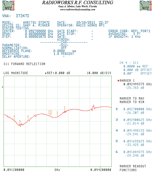
Though the slug solution did improve the overall Return Loss by a few dB, it did not improve the linearity over the +/- 200 kHz bandwidth and it did not improve the center frequency Return Loss to any appreciable level.
Finally, figure 3 easily reveals that there is a proper tuning solution.
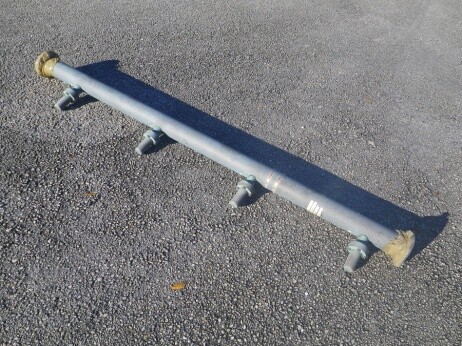
This best solution involved replacing the 6-foot long single-slug section which contained a single factory field selected slug, with an actual 4-portal tuner which is the twin to the one in the above photo.
The tuner selected was a unit that came from a different random manufacturer, was used, and was not hand selected for any range, frequency or manufacturer – it was simply a direct size replacement of a 6-foot length with four symmetrical and equilaterally spaced plunger-type tuner elements on threaded posts with locking clamps.
The result, in figure 3, shows a center Return Loss of -41 dB with the +/- 200 kHz symmetrical sideband widths at -30 dBm and -29 dBm respectively. This gives a nearly ideal symmetry and linearity which is fully capable of supporting full bandwidth FM HD transmission, while either of the results in figures 1 or 2 would exhibit serious range and analog L-R issues for imaging.
In actuality the raw antenna of Figure 2 would have been a better solution than the slugged one. The essential question is what depth of return Loss would you be happy with?
THE REASON
The statement that slugs are narrow-minded is a provocative way of stating that the reach of effect of the slug is applied to the Smith Chart in literally one desired frequency which results typically in a minimal bandwidth effect.
The fringe effects of a slug, plus or minus the desired center in any given electrical environment is an accidental consequence to the environment and is never repeated from system to system, as calculations made by the software analysis program base the result on a center frequency – with the changes in the adjacent sidebands acting almost as collateral damage.
Often I run into, with alarming regularity, such less than ideal solutions that are caused by either laziness or a lack of desire to open the line “one mo time.”
Actually, the notion of inserting more than one slug is not contemplated by anyone’s result solution software to be able to create a solution without running multiple iterations of the software in sequence once the first solution would be calculated, tested, measured and then re-run over and over again. This, of course, means you keep opening the line and playing with the insides.
If this sounds like a great way to get to Oz, go for it. I assure you, the tuner is easier, faster, and will never let you down.
PROOF
As the slug acts on the Smith chart in only one very narrow radii, the multi-ported tuner has the ability to simulate both the venerable narrow slug as well as multiple smaller or continuously variable size slugs.
These simulated slugs (portals) are continuously variable in both location and mass (volume) by virtue that multiple portals extend typically over a half wavelength of transmission line. Because of this versatility the plungers can be moved in or out of proximity to the center conductor to simulate the various amount of slug needed, and because there are usually two to five of them, the location of the slug can be constantly shifted.
Those of you familiar with 4-portal applications will realize that a 4 or 5-portal tuner will use anywhere from 0 (zero) plungers inserted to no more than three plungers inserted.
USING THE PLUNGERS
These solutions could be a combination (in the case of a 4 port-unit) of say 2 only, 2 and 1 only, or 1 and 4, only, or 2 with a bit of 1 and 4, or possibly 1 and 4.
Suffice to say the combinations may contain up to three plungers. The idea that both 1 and 4 or 1 and 5 may be used is that the 2 end plungers overlap in repetitive wave radians and they are electrically adjacent just like any other consecutive pair of plungers. In the case of the solution above in Figure 3, three plungers were used in successively lower levels with one toward an end being the heaviest application.
If you ever use more than three plungers, chances are you messed up or have bigger issues.
[the_ad id=”2909″]
TIMING
With the advent of some very special software developed by one manufacturer for use in the selection of a single slug solution, the slug selection event typically lasts an hour or more from start to finish.
This of course assumes that subsequent runs of trial and error are not hampered by struts or girts that apply errors to the solution due to physical lengths or placement on the tower. Directional systems with parasitic elements do further complicate these issues.
In contrast, a multi-portal tuner typically takes about 30 minutes to achieve a final solution.
Just the lack of having to open and re-open the line to play with the slug is critical. Allen screws or magic yellow high-temperature tape can let a greasy-fingered crew corrupt the bullets, teflons, and innerds of the adjacent components to further exacerbate a future potential for mishap or later fire from crushed bullet fingers or “wallerd out” inners from repeated installation.
FLEXIBILITY
Another of the inconveniences of internal tuning devices like slugs is that if the conditions around your antenna change, you are going to have to usually bring in the factory, open up your line and play with the slug, and perhaps its size, again.
In that case, I say bring in the factory since not many independent antenna consultants ride around with a few thousand dollars worth of Steatite in their kit.
In practice, I usually keep nearly a half dozen pieces on hand, but rarely have just the right one with me. New lighting conduits, additional transmission lines, re-strengthening and replacement of struts and girts all play havoc with your tuning.
If you have a nice adjustable multi-ported tuner, you just trot a tower guy up the stick and less than an hour later – with your precious nitrogen still inside the line – you achieve a new and optimum tuning solution and never risk humidity or insect infestations.
Take 30 seconds and sign up here!
Return to The BDR Menu