

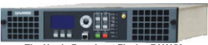
The Harris Broadcast Flexiva FAX150

[August 2013] In the past few years, we have seen a number of low power FM transmitters, taking advantage of new manufacturing techniques. As a bonus, these products can be easily adapted for the expected demand transmitters for LPFM. Alex Hartman takes a look at one of the new Harris Flexiva models, the FAX150.
Harris Broadcast, as they are known these days, is once again trying to re-invent itself.
The Harris brand has been a staple in the broadcast industry worldwide for decades and, while there have been some mixed reviews about the “old” Harris, the broadcast community has come to expect nothing but the best from them. Admittedly you do not hear much about them when their products are working well – which is much of time – like me, most of us only go to visit them when they are broken down.
Over the years, I have become very familiar with the Harris line ranging from the older FM series up through the Z series. My main transmitter for KVSC-FM is a Harris Platinum Z5, installed in late 2003. It has been mostly solid since day one; like all transmitters, it has a quirk or two of its own.
The Flexiva Fax
Compared to anything Harris has ever done before, the Flexiva series of FM transmitters really is a complete re-design and implementation, taking full advantage of the latest digital broadcast technology.
I will say, upfront, that with a caveat or three they have done a good job with the FAX series.
The sheer size – or lack of – is the first thing people will notice. You can cram a full 20 kW unit in just two-thirds of a standard rack. And 40 kW will fit in two racks, with room left over for a few items as well.
The Look Up Front
The front of the unit looks very clean.
The main control panel has been kept quite simple and effective with all the goodies living in 2 the GUI. There is an LCD screen with a blue background with white text over the top.
The front panel switches are “bubble pop” type switches and, although a bit mushy and require strong pressure to activate, they give good tactile feedback when pushed; they make a little “pop” sound when engaged. However, once installed, most users will use the GUI to configure and operate the unit from there on out, unless they are doing some work at the plant.
Navigating the menus from the front panel is done with a 4-way “D-pad” and an enter button in the center. From within the menus you can set power output, feature options, frequency, IP information and several other features. If you forget your laptop at the station, you can still have plenty of control over the unit from within the front panel.
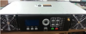
The cover for the front of the unit contains a washable filter for the two fans which run on either side of the main controls. One blows air over the PA brick and the other feeds air over the power supply and main parts of the chassis. The fans only run when the unit is generating RF. The fans themselves are not horribly noisy given the CFM they can move.
As with all transmitters, there is a switch for local and remote. This also locks out users from making changes from within the GUI.
The FAX150 is a quite small, 12 inches deep, and fits in a standard rack before the RF connector. As always, it is a good idea plan to add a few extra inches for an elbow or a spot for the coax to route itself to whatever it is going.
The unit’s weight is impressive as well. Most people used to say you could judge build quality by its weight. Today, while that can be true for some things, it is not true anymore with electronic devices. The FAX150 weighs in at just under 15 pounds. That is a lot of power for very little weight. Not that people use transmitters for strength training, but if you are trying to work on the unit by yourself, it is very easy to handle if you pull it out for service.
Full IP Connectivity
Two items that have come to be expected on new transmitter designs is an Ethernet port and a web-based control/status interface.
Harris does not disappoint, providing not one, but two Ethernet ports. One is for system administration and permanent installation, the other is designed to be a “quick service” port on the front of the unit.
The web-interface itself is very intuitive and arguably one of the best designs that could be made. It is based on a very simple block diagram layout with which every engineer is familiar.
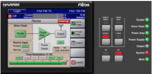
Although it does not give you a pretty spectrum analyzer for the RF or a constellation of the audio, it does give you plenty of metering from audio to the RF stages, including temperature sensors pretty much at every point from AC in to RF out, to control any over-temp situation.
The display quickly tells you what is right and, more importantly, what is wrong.
The GUI also has a line of “idiot lights” along the right-hand side, laid out exactly like on the front of the unit. Green means good, red means bad. It is the nitty gritty.
All-in-all, a very simple, but elegant solution for at-a-glance troubleshooting.
On the other hand, a VFD would have made reading the screen a little easier to my eyes, as blue/white text can get hard to read when you are not looking right at it. If it is set up a little higher or lower than head level (which is possible) it can get washed out and harder to read. A timeout value on the backlight would be a good idea as well as these little LCDs are notorious for “burning out” over time.
Another item I would have liked to see on both the Ethernet ports is status lights like you would find on a switch or your computer showing link status and traffic. Those little lights are very useful for diagnosing Ethernet issues such as bad cabling or perhaps when a lightning strike may have killed the controller. Without the lights, you are guessing.
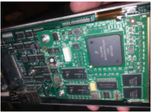
Taking a Look Inside
Now, let us take a look inside, at the meat and potatoes of the FAX150.
When you pop the lid on the unit you will notice just why it is so light. It is a pretty compact little guy.
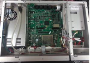
There is a main board with the RF generation section, an audio section, and a little RF out going into a PA brick on the right side in a walled-off cavity for RFI suppression.
The board looks very well thought out. There are no budge wires anywhere – if they made a mistake, they re-spun the board and did it right. A 3 dB attenuator links the main board to the PA, although I would have expected this to be a firmware controlled item.
In my demo unit that attenuator can get pretty warm with no active cooling nearby. Fortunately, Harris has seen the need to make a production change, and the attenuator has been removed in favor of a more efficient IPA/PA transition via firmware. Additionally, most power levels now feature an improved airflow design to keep the modulator compartment at a proper temperature level.
The Brain Center
Directly behind the LCD panel is the “brain” of the entire transmitter, an embedded PC hiding on a card back there with both Ethernet ports and all the guts of the GUI.
The designers went with a Freescale Coldfire 5484 CPU that runs at 200 MHz with 64 MB of RAM and 4 MB of flash space. Given today’s integrated ARM CPU options, this choice is a little surprising. 200 MHz is not a lot of power to do things like AoIP processing or other more CPU-intensive tasks. While it is not trying to do general computing, it does limit what the FAX is capable of on the front-end.
I would have liked to see something along the lines of an i.MX CPU which gives a lot more I/O options for future expansion and capability. However, since they have gone with a MCU on a card, upgrade options are available should they decide to implement any revisions.
One thing is for sure, Harris Broadcast software developers have to keep their code lean and clean to make the best of the 200 MHz available in the FAX MCU.
The Field Programmable Gate Array (FPGA) on the main board doing most of the heavy lifting is a Xilinx Spartan-6, a very good FPGA for broadcast uses. Harris Broadcast has relied on this FPGA for many other items including their studio equipment. I would suspect that if they implement any AoIP solution, that the Spartan is more than ready to handle it.
One slight concern is the sparse RFI shielding on the PC portion. In high RF plants, this could cause issues. My preference would be to have the CPU hiding inside the main chassis somewhere on a riser stand-offs to keep RFI at bay.
The Power Supply
Moving on to the power supply, Harris Broadcast has chosen to use a Mean Well switching supply model SP-320-48. This is a 320-Watt, 48-Volt supply that can accept 90 – 260 VAC input at 50-60 Hz, meaning that it is a “worldwide” capable supply.
The power supply fan does run all the time, even if the exciter is “off,” to provide sufficient cooling for the unit. On the 150, the PSU is integrated, on the larger models however, they are swappable. This supply is rated at 89% efficiency from AC to DC from Mean Well.
From AC in to RF out, the FAX150 model is rated at (up to) 52% efficient. I would have liked to see some ferrites on the AC line internally for protection. This is an inexpensive insurance policy that I recommend all broadcasters should invest in and install.
Connectivity Plus
Harris left their options open when it comes to expansion inside the FAX150.
On the backplane of the FAX150 is a whole host of connectivity. IEC mains power, ground lug, analog audio in, AES audio in (2), GPS input, SCA inputs (2), composite outputs (2), an external RF input, N-connector main RF output (7/16” DIN on bigger models), a Subminiture Version A (SMA) “RF sample” port, 10 MHz in, 1 PPS Reference, 19 kHz pilot out, Ethernet, and DB connectors for integration into any plant’s meter and control layout.
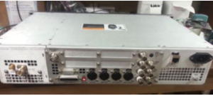
As of this writing, the FAX does not do HD internally; you still have to use an external exciter. Still, there are quite a few unpopulated connectors on the backplane for Mini-PCIe, SATA, JTAG, Serial, a connector labeled “Orban” for a processor expansion board now said to be available, and a large proprietary connector that will be used for an HD Exgine in 2014 as well as other features planned but not yet announced.
The only connector noticeably missing from the FAX150 is a USB port, something I would have expected to see since USB is so useful in many respects from reloading firmware files to backup audio, processing presets, and local log retention.
Audio Inputs
If you have trouble getting audio into this thing, you really have other issues.
There are several different methods of delivery from composite to Analog L/R to two different AES sources. You even can have two exciters running in primary/backup configuration as a “just in case.
I would have liked to see an Axia or WheatNet delivery method – or some other IP audio source. I imagine that can be added in future firmware releases. Some might argue that it is not needed at the TX level, but others will attest to its value when setting up an LPFM or translator. (The FAX150 series up through 1 kW is pending type-acceptance by the FCC to be used for LPFM.)
The Harris FAX also does something not many other vendors want to implement: audio failover – and auto restore.
If you lose audio on your primary source, say main AES, for some reason, you can have the unit fail over to an analog (or other AES port) source automatically. Then after a configurable amount of time once audio has returned to the primary source, it will go back to the primary audio all on its own.
Of course, this can lead to weird effects on the air, especially if, like me, you have two completely different sources for primary and backup audio. If the primary audio source is “bouncing” due to weather or failing STL equipment, it will sound weird. On the other hand however, you are still on the air, not throwing a dead carrier.
To make audio processing easier, I am told that in the near future there will be an internal HD generation board and an “Orban Inside” processor similar to the Nautel line.
With these additions, this would definitely make the FAX series a “one-stop-box” type of rig. It would take the guesswork out of setting up a HD plant and/or an audio processor to boot.
Some argue that it is a case of putting all your eggs in one basket, but sometimes that is what is required when space in the TX suite is at a premium.”
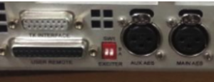
Multi-Use Capabilities
Integrating the FAX into an older transmitter as an exciter replacement is not too difficult with a little bit of forethought.
A two-position dip switch on the back of the FAX150 changes is all it takes to change it from master transmitter to slave exciter mode.
I wired the FAX150 into my Z5 in place of the DIGIT-CD exciter. As many know, the Z-series transmitter is very particular about control and status from its internal components.
The design engineers kept with the similar DB15 female connector to integrate into the newer Harris line of transmitters. I had no problem wiring up a cable from the FAX and letting my Z control it from its main processor card.
The Listening Test
“So, Alex, How does it sound?” In a word: “crisp.” Compared to my DIGIT-CD exciter, there was a noticeable audio difference. Among the first things I noticed, the high-end was more pronounced and sharper than the DIGIT-CD.
Even without a processor in front, you can plug audio straight into the unit – and you will be on the air. Barefoot, you will not be the loudest, but the FAX150 is very clean – and modulates up to 100% without breaking a sweat. The built-in limiter will make sure you stay within legal limits.
The FAX150 also features a built-in static RDS/RBDS generator, providing TP, PI, PS, PTY, RT, TP, and 7 AF channels, per the IEC 62106 RDS standard.
Given that RDS/RBDS is just text data easily obtained via either of the Ethernet ports, I would like to see added DPS capabilities in a future firmware update; with the computing power built into these new digital exciters, you should no longer need any external encoder.
A Quibble or Two
The one thing that bothered me a bit is the use of the SMA sample ports on the back and front of the FAX150. Although the RF port on the front could be handy for diagnostics, it really is not necessary.
Harris notes SMA ports are there to meet international requirements. Still, while they do save space, not many broadcast people have SMA adapters in their kits. I would prefer a good old BNC. The point is that having non-standard adapters and extra cables can be an issue if some is trying to troubleshoot the unit. I am pleased to know Harris is considering adding a BNC connector in the future.
Another personal preference: I would like to see the backplane DIP switch put inside the chassis, as it is way too easy to bump it where it is now. (Also, dip switches do tend to get a mind of their own after a number of years living in a transmitter shack and can create interesting and long nights of trouble-shooting weird issues.) But if you are mindful of it, you should be okay.
World Class
Overall though, I have to say the “new” Harris Broadcast has done quite well with the FAX line of transmitters. It is a very good starting point for the company.
Given that the Harris brand is recognized worldwide as an industry leader, it commands quite a price tag as well. The FAX150 demo unit I was sent as configured (no options) from SCMS is just under $8,000 USD before any discounts or preferred customer pricing – on the high side of its class. However, I am sure it is much more competitive after such adjustments.
With a few tweaks and some additional features like those I outlined above, it will be a very competitive product in the field.
– – –
Alex Hartman is a contract engineer, based in St. Cloud, for a number of stations in Minnesota, including KVSC-FM. Contact Alex at: goober@goobe.net