
The Difference and Why It Is Important

[January 2017] Most broadcaster engineers try hard to present a signal as clean as possible, so the listener can hear the audio as close to the way the artist intended.
However, it takes hard work, especially on the program audio to be successful. Even small differences in the audio as it moves though the program chain can make a big difference, as Tom Osenkowsky demonstrates.
“What a diff’rence a dB makes” (with apologies to Dinah Washington and Esther Phillips). Actually, though, I am referring to the difference between two signals – usually referred to as Left and Right – in the broadcast plant.
By noting and analyzing the levels of these signals, we can learn a lot about the performance of the equipment through which it passes.
Identifying Distortions
Figure 1 shows a popular distortion analyzer. It is being fed a nominal signal at a slightly elevated level, for the purpose of our analysis.
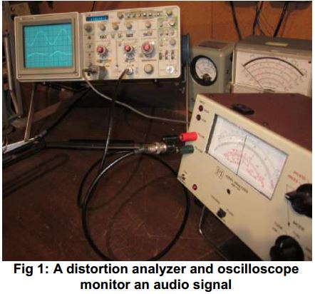
The analyzer is set to read Total Harmonic Distortion (THD). The principle of operation is simple. A low distortion sine wave serves as the input to the device under test. The THD analyzer is connected to the output and is adjusted for a minimum indication with the controls properly set.
This minimum indication results from nulling out the fundamental frequency (input signal).
Basically, an attenuator is adjusted until an on-scale reading is obtained and the percentage of distortion or amount of signal relative to the input is read accounting for the amount of attenuation selected. In the photo we can see the analog meter reads about 1.4% THD.
As noted, the oscilloscope is connected to the output of the device under test and the analyzer. The top trace shows the output signal of the device under test.
You can see that I have intentionally slightly overloaded the device to produce a small amount of THD.
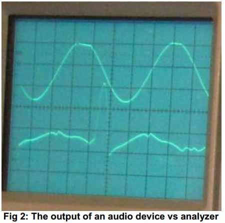
Examining the output of the analyzer can reveal problems that are not obvious when looking at just the output of the device under test.
The lower trace on the oscilloscope shows us the analyzer – the difference between the output less the nulled out input signal.
This information can be very helpful in trouble-shooting.
Of course, often the THD is not that at all. It can be noise, power supply ripple, or audio leakage from another source – really, anything other than the original input signal.
L+R and R-L
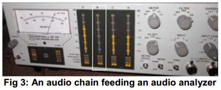 Figure 3 shows an output display of an audio processing chain. The source is a mono CD. The telltale sign of mono is seen by the lack of L-R indication on the second bar graph. Since L=R, then L-R equals 0 – and no output.
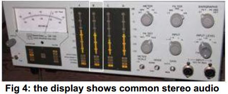 Figure 4 shows the same device while monitoring a stereo CD selection. A lower amount of audio is showing in the Left channel (third bar graph) and the L-R confirms this – a result of unequal amplitude and phase between channels.
As you can see, when comparing performance between audio channels monitoring the difference between them can be very telling. The difference should be zero over the entire spectrum of interest when fed the same source and adjusted for identical gain.
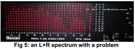
Figure 5 shows the audio spectrum display of a stereo CD source which produces a phase error when summed to mono. Notice the dip in the response at 5 kilohertz. This is easily distinguished as phase error when listening in mono.
What’s All This About Mono
Why is mono important?
Stereo image enhancers can sound very good in a home listening environment, however, in a car the listener is not centered about the speakers and separation is not easily recognized.
In FM automobile receivers the separation will automatically blend to mono and the high end attenuate with lower received signal. This feature is incorporated into the receiver to reduce static.
The automatic blend to mono can result in decreased loudness due to the summing process. QSound was a three dimensional sound processing algorithm employed on several popular albums by Madonna, Pink Floyd, Paula Abdul, Luther Vandross, Sting and others. Its lack of mono compatibility made it ultimately unsuitable for broadcasting.
Mono compatibility is therefore very important.
Differences in the output of a turntable preamp while playing a mono test record or mono recording can indicate a simple imbalance in output level which is simple to correct or a defective component in the RIAA equalization circuit.
For a tape source it can indicate a misaligned tape head or amplifier issue. (With the trend toward digital storage this is less of a concern today than in the past – although it has happened that some stations dubbed out of phase audio to their hard drive!)
As you can see even a small difference between channels can make a lot of difference when it comes to the overall sound of a station.
Good Audio is the Result
It can be very telling.
I once had an FCC inspector show up at 3 PM on a Friday afternoon. This was a beautiful music FM station in CT. He asked if I did an annual audio proof-or-performance (which was then required).
As I reached into the file cabinet to retrieve the paper he said he did not need to see it; he just breezed over it. On the way to the transmitter I asked him why he did not closely examine the report. His response was that he noticed I kept the stereo modulation monitor in the L-R position.
He said when the announcer was speaking the needle did not even move.
He said if I paid attention to that he was certain we would pass a proof.
– – –
Tom Osenkowsky is a well-known engineer and consultant. He has written a number of technical programs for computers and serves as an Editor of the NAB Engineering Handbook. You can contact Tom at tosenkowsky@prodigy.net