Regular Frequency Measurements Can Save the Day

[August 2012] A lot of what a broadcaster engineer does is often not spelled out specifically in the Rules. Many times it comes under mantle of “Good Engineering Practices.”
Among these GEPs is regular preventive maintenance – anticipating problems. Making regular frequency measurements is part of that GEP.
Many stations today actually have operated for years without ever checking their carrier and/or subcarrier frequencies, much less the STL or RPU transmitters.
After all, with digital carrier generation, everything is much more precise than during the days of heated crystals that multiplied their fundamental frequency nearly 1000 times to reach the station’s operating frequency.
So, is that enough reason to trust that your transmitters are always on frequency? Or should you read further?
The Rules According to the FCC
While the FCC long ago removed the daily requirement that stations log and verify their frequency, they have never removed the requirement that stations will be held continuously responsible for compliance with the FCC Rules.
That means that since the FCC removed the requirement that stations log and verify their frequency daily, frequency (and modulation) monitors are not required to be in a station – and indeed have virtually disappeared from many stations.
Nevertheless, the underlying legal limits are still on the books, and stations are expected to be in compliance. By the way, that also includes all of a station’s RF gear, including STLs, RPU, and 2-Way gear, etc.
For some stations, given the age of their transmitters, components might well have changed values enough to cause the transmitter to exceed legal limits. Still, it is not only older gear that can go off channel.
Stuff Happens
Experience clearly shows that “stuff” happens and transmitters may indeed wander out of tolerance if they are not monitored regularly. 2 For example, during a routine frequency measurement, one FM station was found to be nearly 50,000 Hertz off their assigned frequency.

The station had not even noticed, as digital receivers had no problem following the station. Fortunately the problem was discovered and corrected before the FCC discovered it.
More Than Occasional Events
Then there was the station whose listeners called in saying they could not get it on the normal channel – their digital receivers indicated the station was two channels higher up on the dial!
Obviously that situation was an alarming call to action. Fortunately, that station was able to switch quickly to a backup exciter while a factory update was installed in the main exciter, solving the problem.
Another strange case several years ago turned on an exciter from a well-known manufacturer would go off frequency under high modulation conditions, depending on whether the front panel bar graph was set to “dot” or “continuous.” It turned out that a fully-lit bar graph was loading the 5-Volt power supply just enough to cause the problem.
Other causes for odd frequency transmissions involved things like input off-set voltages in digital exciters or exciters jumping to a different channel due to dirty dipswitches.
Frequency Tolerances
With these interesting situations in mind, let us take a look at what you need to know.
By way of quick review, the FCC Rules tell us:
- For AM carriers, the maximum departure from the assigned frequency may not exceed +/- 20 Hz
- For an AM Stereo Pilot, the maximum departure may not exceed +/- .1 Hz
- For FM main carriers, the maximum departure may not exceed +/- 2000 Hz
- For FM stereo, the 19 kHz pilot frequency departure may not exceed +/- 2 Hz
- For 950 MHz band STLs, the allowable departure may not exceed 10 kHz.
- For RPUs the allowable deviation will depend upon the emission and power.
- For TV visual carriers, the frequency departure may not exceed +/- 1000 Hz and the Aural Carrier may not exceed +/- 1000 Hz from the actual visual carrier plus exactly 4.5 MHz.
- DTV signals are held to a tolerance of +/- 3 Hz depending on whether or not there is a first adjacency lower side NTSC TV station (There still are a few out there). This gets tricky at 500 MHz and up.
Frequency Measuring Methods
There are several commonly used methods to measure frequencies accurately.
The most obvious method is to measure the carrier directly out of a transmitter with a frequency counter. If you are going to make carrier measurements at an AM transmitter it is best to measure from a pre-modulated stage; some AM transmitters even provide a “spigot” ahead of any modulated stage.
Measuring a stage after modulation can produce false readings because frequency counters count the number of pulses they see in a very exact window of time. High negative peaks can cause the incoming carrier or pulse train to momentar- 3 ily drop below the threshold level of the counter and miss some pulses resulting in an erroneous reading on the low side. If the threshold is too sensitive, a counter can sometimes count stuff in the upper and lower sidebands in addition to the actual carrier frequency.
A problem with measuring an FM carrier under modulated conditions is that instead of measuring what is supposed to be the carrier “at rest,” you are really measuring the “center of modulation.” This is the reason the FCC wants to measure FM carriers without modulation.
There are some other interesting problems that come into play when measuring the frequency of an FM carrier.
Almost all the current exciters are direct FM devices where the audio modulates a Frequency Modulated Oscillator (FMO) that is corrected by some form of AFC. While the exciters are usually “phase locked” through a comparatively long time constant to a crystal reference, they are not “hard locked” to that reference.
As a result, the AFC circuit has to keep chasing the oscillator around due to modulation and try to corral it back to where it belongs. This can be seen on a spectrum analyzer or by looking at the AFC correction voltage applied to the FMO with a DC coupled oscilloscope.
Do It Yourself?
There was a time when, just after the FCC did away with the rule, stations would buy the newly available $250 frequency counters and ran out to the transmitter building to save money.
The only problem is that these handheld counters often were often quite far out of calibration when received – if indeed the unit was capable of sufficient stability to be calibrated for broadcast use.
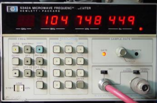
To do it today it might take $5000, plus regular calibrations to buy and operate a suitably accurate counter – perhaps a bit much for some stations to fit into their budget.
On the other hand, a number of DVMs, service monitors, and spectrum analyzers have a built-in frequency counter function. Yet, would you trust the accuracy of any of these to be enough to prevent a NOV from the FCC?
Avoid Assumptions
With such tight tolerances, particularly in the case of DTV signals, GPS (Global Positioning Satellite) signals is a must.
With the advent of GPS Frequency and Time Standards the calibration procedures have become a lot easier – but have some pitfalls.
Perhaps you are inclined simply to rely upon manufacturers to build in GPS signals as frequency references. But it could become a costly mistake if you rely on a GPS reference without periodically checking it.
A while back I was asked to verify the Digital Pilot Frequency of a new DTV facility. The station was required to be within 3 Hz of a specific offset. I measured them 12 Hz high. How could this be? Both their transmitter and counter were locked to the GPS reference, just as I was!
It turned out their GPS receiver was not locked due to interference to the GPS receiver at their transmitter site. However, since they were using the same GPS unit to calibrate their counter and the transmitter, the errors cancelled each other, leaving an erroneous “good” reading.
For that reason, I strongly recommend against using the same GPS receiver as the source for your carrier and your counter. Additionally, make sure the GPS reference is indeed working properly; some GPS devices just do not tell you enough about their true condition.
Double-Checked Accuracy
The proper calibration of frequency measuring equipment can be time consuming. In the past it was satisfactory and accepted practice to calibrate against the National Bureau of Standards 4 (NBS) signals by way of WWV on 5, 10, 15, or 20 MHz.
This works for typical AM, FM, and VHF-TV carrier frequency measurements, but depending on where you are in the country, Doppler and other propagation anomalies easily can cause calibration errors by 2 or 3 parts per million. By the time you transfer this to a FM signal you can easily have an error of several hundred Hertz. At UHF-TV frequencies, the error becomes totally unacceptable.
WWVB at 60 kHz has a higher accuracy. But by the time you get through the on-going process of calibration and maintenance you will have discovered you do not own a frequency standard, it owns you. Like parenting, it is a time consuming process that never ends.
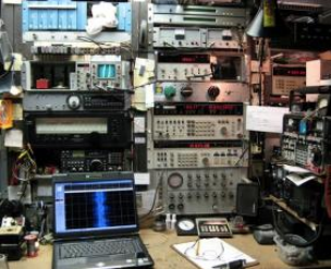
My counters are all GPS referenced, using two GPS systems monitored by a phase comparator connected between the two – it alarms if they disagree.
Another potential “gotcha” that needs to be considered: While a DTV transmitter itself may be GPS referenced, the data stream may directly affect the pilot frequency’s position. Recently a station upgraded a converter at their studio. This seemingly simple change resulted in their pilot frequency moving 7 Hz outside of their 3 Hz tolerance.
For some of those very reasons, over the years many broadcasters have come to rely on outside frequency measurements services to assist them in maintaining compliance with the Rules
A Preferred Method
The most reliable method is called the Heterodyne Method. It affords the best confidence with extreme accuracy as well as being the easiest off-air method for both strong and very weak signals. Because I am seldom at a transmitter site to make carrier frequency measurements, I normally use this method.
For heterodyne frequency measurements you basically need three things: a detector (receiver) with a good zero-beat indicator, a stable transfer oscillator to accurately zero-beat signals and an accurate frequency counter to measure the transfer oscillator.
In the Heterodyne Method the transfer oscillator is adjusted to exact zero beat with the carrier. The transfer oscillator is then counted with the frequency counter to determine the carrier frequency. The Heterodyne Method can also show you problems not visible with a counter alone – for example, one FM station was dithering about 6 kHz in frequency, near the edge of AFC lock. They did not see this because their counter was averaging the dithering.

I normally use an HP-3336B for frequencies below 30 MHz; for frequencies near or above 30 MHz I use a highly modified Ailtech/Singer model CSM-1. The transfer oscillators are also GPS referenced but to a different system than for the counters.
The transfer oscillator is also fed into an adjustable attenuator and combined with the incoming received signals at the input to the receivers. Then, attenuators are adjusted to give the best ratio of signals for the most pronounced beat indication. Many times on very weak signals I find the best results are obtained in using a FM detector.
With the right ratio there is a very audible square wave or switching that occurs as you approach zero beat.
Since not all signals to be measured are local, a variety of antennae and receivers are necessary. I use a Sansui TU-717, a Marantz model 707 car Stereo-AM receiver, a HP-3586B Selective level Voltmeter, an ICOM R-7000, and an IFR1500 Service Monitor that is GPS referenced. At my location, I also can hear many of the local 900 MHz STL transmitters.
If I can detect it, I can measure it.
It Just Makes Sense
So, nu, after reviewing the above, why would you use a measuring service?
Over the years my clients have felt it is more productive to use a reliable outside frequency measurement service on a regular schedule.
Using an outside service saves them from having to spend their time and manpower to make the measurements as well as to maintain the equipment and standards necessary to meet today’s requirements.
Over the long term, these reports also provide good documentation should there be any unexpected problems. And they assist the client in meeting their required FCC compliance.
Importantly, if an FCC field agent were to show up, those regular measurements can go a long way in showing your intent and good engineering practices – or at least the effort to use GEP – should an out of tolerance condition arise.
It just makes good sense.
– – –
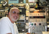
Burt Weiner Associates has been serving the Los Angeles broadcast community for many years. His web page is: www.biwa.cc
