Giving Attention to Coax Switchers

[October 2012] If your main transmitter failed, would you have confidence that your coaxial switcher would quickly and safely connect the auxiliary transmitter to the antenna? If not, it should be high on your “To Do” list.
Obviously, the main transmitter is designed to stay on the air continuously. However, what about those times when you want to do maintenance without rushing through things – or if there ever is a failure on the main transmitter? That is when you need a reliable coax switcher.
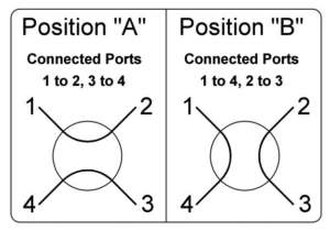
A coax switch provides a convenient way to switch two different RF sources to two different output loads.
There are many thousands of coax switches in use today. Some are manual – literally patch panels – and others are motorized. Having a good motorized switch can be the difference between staying on the air and a long trip to the transmitter site while listening to static.
Another important reason for a switcher, even if there is no auxiliary transmitter, is being able to switch to a dummy load and immediately determine if the trouble is in the transmitter or the antenna system.
Selecting the Right Switcher
The most flexibility comes when you have two different transmitters, main (1) and back up (3), and two different loads, antenna (2) and test load (4).
Choosing the Right Switch
Choosing the right type of coax switch is not as simple as just matching up to the same line size that the switch will be used with.
Coax and waveguide switchers are available from several companies, but Myat has given special attention to what broadcast engineers have identified as the key features they expect to see and developed a new line of motorized coax transfer switches.
For example, during our study of the market, engineers told us they set a high bar of quality for their switchers. They want to see the best possible contacts, providing a more accurate and positive connection with a higher power rating.
A Quick Checklist
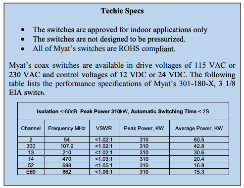
Myat broadband switches are now available in four sizes, 3 1/8 EIA, 1 5/8 EIA, 7/8 EIA and 7/16 DIN. The frequency and transmitter power determines the appropriate switch size.
 The key factors that need to be addressed are:
- What is the frequency or channel of use?
- What is the transmitter power level that will be going through the switch?
- What is the altitude of the transmitter site?
All coax switches in the marketplace today have a power de-rating factor when you compare them to the power rating of a standard piece of rigid transmission line. This is due to the internal switch contacts, which are different than a standard line anchor connector connection.
Myat’s power rating for its coax switches is 15% less than the power rating of standard coax line. High altitudes (typically those sites above 3000 feet AMSL) also have an effect on derating the average and peak powers.
Charts are readily available that provide the frequency and average power ratings for all coax sizes.
Power ratings decrease as the frequency of use increases. For example:
- 3-1/8 coax has an average power rating of 55.75 kW at 88.0 MHz
- 3-1/8 coax has an average power rating of 50.37 kW at 108.0 MHz
- Myat’s 3-1/8 coax switch is rated for 42.8kW at 108.0MHz
It is always best to consult with the manufacturer to determine the correct size coax switch for your installation.
Understanding Switch Design
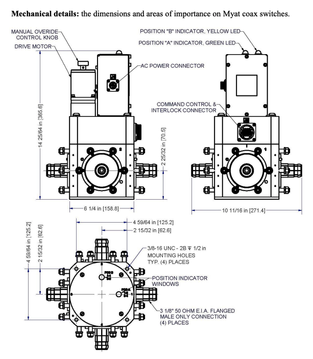
The Myat coax transfer switch has been developed in a radial four (4) port configuration.
Each port is a 50-Ohm male only interface configuration with bullet connector. The outer housing of the switch is aluminum, protected by an application of Chem-Film coating. The inner conductor pathway is silver-plated brass and copper to minimize electrical losses.
The motorized actuator utilizes a high quality, reversible, motor and engineered Geneva drive mechanism to insure accurate 90° rotation of the switch. The switch locks in place at the end of each movement and will remain in position until it receives a signal to “switch” – at which time it will unlock and rotate to the alternate position.
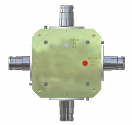
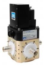
(The red dot shows the unit is in position “A”)
The switch has two window ports located in the base, (either A or B), which use a mechanical flag to indicate the switch position. Position indicator LED’s are also provided on top of the switch control box.
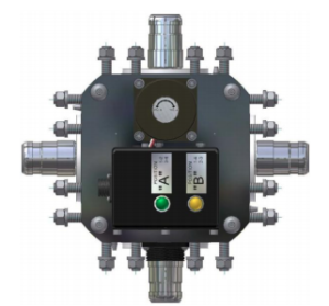
A manual override is provided so that the switch may be operated in the event of an AC drive power failure. A knurled knob is provided at the rear of the motor housing, which is direct-coupled to the armature of the motor.
Interlocks
It may seem as an unnecessary, perhaps over the top warning, but the biggest cause of switch failure is operating it while RF power is applied. This almost always will cause catastrophic failure, requiring the purchase of a new switch.
That means it is critical to install the interlock wiring, and ensure the transmitter has removed the RF before the switch begins its rotation.
In other words, do everything you can to avoid this expensive mistake.
The transmitter interlock wiring is utilized to shut down or mute the transmitter in the event that the transfer switch is mistakenly operated while RF power is applied.
For that reason, each Myat coax switch is provided with three DPDT interlock switches per position for the customer’s use and which should always be wired to the transmitter logic. When wired properly these interlocking limit switches, which trip as soon as a switch command is given, will shut down the transmitter before the RF switch begins to rotate.
In the case of loss of AC power the switch will remain in position when power is restored.
Manual Operation
If you are using the manual knob, you still must first verify that all RF power has been removed.
Then disconnect the AC drive power cord at the switch. Then rotate the knob manually to end of travel. This will drive the switch to change position.
Manual Mode Caution: Before AC power is reapplied remove the RF power, as upon application of power, the switch will return to the last automated command position based on the position of the latching relay.
Maintenance
Realistically, there is only a limited amount of maintenance that can be performed on the coax transfer switch itself as there are no user serviceable parts in the RF switch.
However, it is recommended the switch be operated monthly – both manually and electrically. During this operation all lights and signaling devices should be checked. If any abnormalities are discerned, it is important to contact the manufacturer to determine the best way to proceed.
Transfer Switch Control
Myat also has developed the X01-180 series Transfer Switch Controller to provide an engineered solution for remote control switch opera- 4 tion. It is designed to be installed in a standard 19-inch mounting rack 2RU’s.
The transfer switch controller operates on 115 VAC power. It provides a control signal to the switch of either 12 or 24 VDC, depending on which controller is ordered.
As standard features the controller has an “Enable Key Switch” which will allow for local or remote operation. It also has position indicator LED’s on the face panel to show switch position remotely.
There are controllers available for operating one, two, three, or four remote coax switches. As the number of switches to be controlled increases, so will the number of position selector switches and the number of position indicators.
It is strongly recommended that only genuine Myat Switch Controllers be used to operate Myat Transfer Switches.
– – –
For more information, check out the Myat website: www.myat.com
– – –
Dennis Heymans is the Manager for RF System/ Filter Product Sales at Myat in Mahwah, NJ. Contact Dennis at: dheymans@myat.com