

The Right Way to Cool the Transmitter

[October 2012] Transmitters – and electronic equipment in general – do not do well when over-heated. Components deteriorate, moving parts develop friction, and wiring can melt. Ensuring good cooling is Dave Rose’s topic for discussion.
Before FM, most AM transmitters were co-located at the studio site.
This usually meant they had better care and maintenance. If they were hot and smoking the staff noticed and alerted the engineer who took care of the problem before it became an off-air emergency. Now many FM transmitters on mountain tops simply are forgotten about until a problem develops, especially if there is no engineer on the staff.
Therefore having a reliable air handling system is crucial to keeping the transmitter on the air.
Pulling the Air Out
Recently I read some material on venting transmitter buildings and was surprised that some engineers still insist on using exhaust fans and pulling negative pressure in transmitter rooms.
Over the years, I have built, tested, and used many different ventilation systems to vent these buildings. I have maintained sites at high elevations which could be cooled using fans and blowers, and others at lower elevations where air conditioning limited the transmitter exhaust from building.
Overall, a completely closed system will work best and stay very clean as well. This is especially true with smaller transmitters or digital types. Let us see why this is so by taking a look at how a ventilation system might be designed.
Designing an Inexpensive System
The least expensive ventilation systems are built around a blower, filter, vent and thermostat. I have designed a number of such systems.
One of simplest is using a blower cage from a forced air heater. These can be found used at the local HVAC company for about $80.
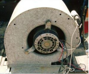
A used blower motor and cage from a heater
Usually the same place has a sheet metal shop that can build the box around it. Have them build a slot for a 20x20x1 pleated filter with a cap or door for filter replacement. It always amazes me how skilled these sheet metal fabricators are and how fast they can take a crude drawing and a squirrel cage and create a professional looking system.
The cost for the metal work will be about $120 for a total of about $200. This box can go on the inside of the building with a gooseneck on the outside or the whole unit can hang on the wall on the outside of the building with a couple of tabs to anchor it to the wall.
Once I got real imaginative and used an evaporative cooler. I pulled out the gear used for the water and installed three 2-inch filters, 20×20 with some pieces of sheet metal strapping them in and sealing it off using self-tapping screws.
The Pitfalls of Exhaust Fans
There are always problems with using fans and a filtered inlet to exhaust buildings.
The primary reason is that fans are unable to draw enough air flow in through the filters on the other side of the building. This causes additional flow to come through every crack and hole in the building – because it is easier to draw from those places than the filter inlet. This allows dirt to be sucked in and results in a very inefficient system.
One result is that the dirt will usually wind up in the equipment causing arcing and relays that will not operate.
Also since a negative pressure is generated inside the building the transmitter is hampered in getting sufficient makeup air, causing a loss of air flow and more heat in the transmitter box.
Worse yet, I still see transmitters venting directly through the roof above them. This sort of vent will eventually end up with leaks that will then drip directly into the equipment.
The Right Way to Handle Heat
The best way to exhaust heat from a top-vented transmitter is to duct the heat laterally through the wall, with a gooseneck on the outside.
As you put the metalwork together, notice that there is some space between the transmitter and the capture hood. This prevents problems if the exhaust gets blocked for some reason.
![]()
The right way to ventilate a transmitter
You will notice there is a dual system in this drawing. Just as the gap on the hood is there to prevent problems if the exhaust gets blocked, a smart installation includes a backup ventilation system such as a second air conditioning unit or, as in the drawing, a fan and a second gooseneck, with a temperature-operated damper.
When putting this sort of system together, it is a good idea to use wire mesh to prevent critters from crawling in through the exhaust vents. And if the transmitter room is co-located with the studio site, make sure it is kept separate from the studio AC and heating. Combining these can cause many different problems.
It is worth mentioning a problem with the new digital transmitters is the way they exhaust heat. Many have vents out the back and front and do not allow for a hood and duct to vent to the outside. In this case I just use a vented goose-neck on the building with a wire mesh to keep furry critters and birds out. Let the transmitter vent directly into the building.
By the way, here is another tip when setting up the ventilation: never draw air from a generator room with a diesel generator in it. The soot will get into the PA and cause arcing.
Heat-Air Flow Calculations and Engineering
To decide on how large a blower or how much cooling capacity is needed, you should stop and calculate the load. Not only consider the transmitter heat and air needs, but also the heat from other equipment, plus back pressure from ducting and goosenecks.
1. The air flow from the building blower (in cfm) should be 1.5 to 2 times amount of flow needed through the transmitter and other vented equipment.
2. Air conditioning should be sized by the total heat produced (BTU’s) by the transmitter and the other equipment in the building. The manufacturer would supply this data.
3. In extreme climates dampers should be used when shifting between AC and building blower systems.
4. In extremely hot climates use two AC units with the second for backup and alternate the units monthly. In extreme cold use a building heater.
5. In extreme wind conditions use baffles on the goose necks to prevent back pressure.
6. New digital transmitters that do not have a outlet for a vent on the top should be vented into the building and then outside via a gooseneck with a critter screen.
Controls, Thermostats, Probes
I have seen simplified control systems that use thermostats that control the blower motors directly. Eventually, however, the contacts of these controls usually start having lock-up problems.
On the other hand, I have had good luck using low voltage control systems with mercury switches. I like to use a 12 Volt DC wall wart combined with a relay which has multiple contacts in parallel, so it will handle the blower current.
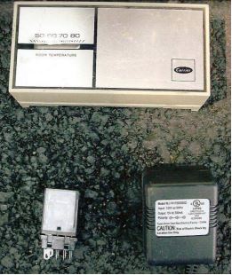
A low voltage gear thermostat,
relay, and 12 VDC transformer
This can be installed in a regular convenient outlet box with the thermostat mounted on the front.
Taking the Temperature
Transmitter’s stressed by heat can lose years of life and cause long term maintenance problems. One thing is for sure: there is nothing like getting to a transmitter site and finding out there is a heat problem by first getting burned by the door knob and then finding the meters melting down the face of the transmitter.
For that reason, I also like to back up the thermostat system up using a separate thermostat connected to the transmitter’s on-off circuit. A Dayton thermostat is all you need.
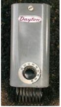
This system shuts off the transmitter if the building temperature gets above 100 degrees F.
Another good solution is to use your remote control system. I use a Sine Systems temperature probe unit that produces about 3 Volts. The voltage can then be sent to a channel on the remote control box, programmed to reduce power or shut down the transmitter before the heat gets too high.
Be sure and check the AC unit to ensure a temperature reset after a power failure. Some digital AC units do not reset automatically, and must be manually done. If there is no other option I have tied into the remote control with a thermostat to initiate a restart when the temperature drops back down.
A Transmitter Site Ventilation Checklist
Here is a checklist of things to cover as you plan how to keep your transmitter cool:
1. Always use positive building pressure using blowers and filtered air.
2. Vent all equipment that is producing heat.
3. Vent the heat through the wall using goose necks (do not use holes in the roof).
4. Always keep a clean building, using a mop and bucket (carry water if necessary). Brooms and vacuums kick up dirt.
5. Never use high pressure air to clean the transmitter (use canned air or vacuum cleaner).
(In addition to the dust factor, high pressure air can lift traces of pc boards. And, of course, never clean the system when power is on.
6. Always have backup cooling system.
For example, lower elevations might use AC with a blower backup in the building; at higher elevations you might do the opposite: use a blower in the transmitter room with AC backup)
7. Always have emergency thermostat that shuts off the transmitter when the building gets over 100 degrees F. – non-powered is to be preferred.
8. Use a temperature probe for remote metering. Most such metering uses 1-5 VDC.
9. Change filters on a regular schedule and test the backup cooling system.
10. Always use low voltage controls with heavy duty relays (no 120 V thermostats).
To sum up, you can see why just tossing a fan in a transmitter room can be a recipe for disaster. Not only sufficient air and heating/cooling handling is necessary, but also sufficient remote metering, emergency backup, and shut-offs are very important.
Never forget the transmitter is a station’s life-blood and needs lots of TLC. Regular visits really are not optional if you want to save yourself a lot of grief!
– – –
David Rose is an experienced Contract Engineer and Tower Rigger based in Ashland, OR. Contact him at davidrose55@yahoo.com