

Finding and Dealing with Spurs

[December 2023] Have you ever wondered why the FCC requires the NRSC measurement each year? Or, has the FAA called concerning interference to ATC frequencies? While the appearance of spurs will jangle your nerves, Ron Schacht says most of the time, the solution is quick and simple.
If you are the keeper of an AM station, you probably know about spurs – those little carriers coming out of your transmitter usually at symmetrical locations on the dial away from your frequency.
AM spurs will get noticed either by a listener who complains that your station is wiping out some station 500 miles away with their favorite football team or when you look at your annual NRSC compliance measurements.
If you have a PDM transmitter like a Gates 1 or 5 or better, you probably know when the PDM filter capacitors go south: your station appears at three spots on the dial – where it is supposed to be, and 60 kHz above and below – where it is not supposed to be.
This is one of the main reasons the FCC requires AM stations to do an “NRSC measurement” each year: catch these spurs and stop them.
(By the way, like the smoke that sometimes escapes from a resistor, I have found the spurs must have weight and mass because when the PDM capacitors in the Gates go bad, they get lighter by weight after all of the spurs have escaped to the airwaves. It must be true: if you replace the capacitors, feel the difference in weight of the new ones vs the old ones!)
Either way, you can fix this problem pronto once you know it is there.
SPURS ON THE FM BAND
FM spurs, though, are another story.
Unless someone complains about interference to another station you may not know there is a problem. (But do not rely on the salespeople to mention it. They love it when your rig is transmitting on 10 spots on the dial “on the air, everywhere.”)
The most common issue is spurs coming out of the FM exciter from – again – bad electrolytics. It could also be an oscillating later stage (IPA or even the PA stage). But there is a way more common cause for spurs, two of them if you have an AM and FM that are co-located – and now with so many AM stations having FM translators, it is very common.
AM ON FM
Put up an FM translator, yea, just stick a 2-bay antenna on top of the AM tower, hang an isocoupler on the doghouse, and fire that sucker up.
Let us say your FM is on 99.9 – a nice round number close to 100 Megahertz (3 meters) – and your AM is a typical local kilowatt on 1400. All of a sudden, you start getting calls that Hip Hop Harry is getting covered over by your Twangy Tom jock on 101.3.
Well, you first blame the listeners crummy radio and ignore it until you also get calls that Twangy Tom on your FM is covering over Politics Paul on 98.5. Hmmm, maybe you had better check this out. So, you go out to your buggy – and if you are like me, move the Burger King cups and old french fry containers out of the way – and tune around.
Sure enough there is your FM loud and clear on 99.9. But it is also equally listenable on 101.3 and 98.5 and if Twangy Tom stops talking for .00001 seconds, you might even hear your AM audio in the background.
Now what.
THE USUAL SUSPECT
Well, actually it is pretty simple.
Most FM exciters composite input have very good stages, are phase linear, and have a response from DC to light. Unfortunately, most exciters do not have low pass filters so it is a wide-open door. Which is why your AM passes right on through and modulates the FM transmitter with the AM carrier just like an SCA.
There are several solutions to this problem. Most of them revolve around grounds and shields.
CLEANING IT UP
The first step is to disconnect the composite audio at the exciter and any SCA inputs you might have like RDS or SCA and see if the spurs go away.
If they do not, make sure the exciter is securely bonded to the station ground system and try again. You might have to even physically move the exciter to a different location, shield the AC line, and use AM toroids on the RF out or the AC in on the exciter.
If the exciter alone is clean, reattach the input the cables on one by one.
Try with SCA only first. If your signal is still clean go to the composite cable and plug it in. Either way, if you find the spurs are only there when either cable is on, make sure the device – whether it is an SCA source, or a composite source such as a stereo generator, or a composite STL – is also bonded to the station ground. Again, you might need toroids on the AC power cords and/or audio inputs, or in the case of an STL, the RF input, if your STL antenna is also on the AM tower.
TIPS TO MAKE IT EASIER
It is important to keep all composite and SCA cables as short as possible.
If you can find it – and finding it is not easy – use double-shielded cable. By double-shielded I mean inner conductor, insulation, shield, either foil or braid, and then another layer of insulation and another braid shield. The two shields do not touch.
If your equipment has BNC balanced use them. The inner shield provided program low, the outer shield is grounded to station ground, sometimes on one end as it should be and, in some cases, both ends (you never know which works best until you try).
In lieu of trying to find this specialized coax, you can get some of that grounding braid, the stuff that is hollow and snake your regular coax through it. Do not let it touch the BNC connectors if you are running balanced but ground it separately to the chassis of the exciter and the signal source, again violating the grounding rule of “one end only is legal” if that is the only way to get rid of the RF (we will not tell the grounding police).
[the_ad id=”10548″]
WHEN RF ENTERS THE WRONG WAY
I was called in on an interesting issue several years ago.
This station had a 5 kW AM and a 100 kW FM. They had a 25 kW Continental transmitter for the FM with a 10-bay antenna on top of one of the AM DA towers. The problem I was called in for was that, at any more than 50% power on the FM, it would just kick off, no overloads, no reason.
Well, after some head scratching and “percussion maintenance,” we found that there was enough finger stock damaged on the cavity door that RF was leaking out and getting back into the 28 Volt control ladder. Replacing the finger stock cured the problem.
BUT WAIT! THERE’S MORE
After we had the rig perking along fine at its licensed 23 kW, I noticed the VSWR was higher than I am used to seeing on one of those Continentals.
I mentioned it to the Chief and he said “yea, it’s always been like that,” and he figured it was AM rf coming back down into the VSWR detector because when he turned the AM off, the FM VSWR went down, which he then demonstrated for me.
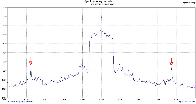
Just out of curiosity I told him to disconnect the composite input from his FM exciter. When he did the FM VSWR dropped to what it was with the AM off. I went out and dug out the spectrum analyzer and took a look. There was his FM carrier as nice as pie with 2 spurs, one above and one below his FM carrier exactly 1.55 Megahertz – his AM frequency of 1550,
In this case, the spurs were only about 30 dB down.
TAKING THE SPURS OFF
This means with an ERP of 100 kW he had 100 Watt spurs – 200 Watts total – on frequencies to which the antenna was not resonant.
The high VSWR came from these two spurs.
We did some better grounding, shortened his composite cable and ran it through a piece of old BX cable sheathing that was lying around and, what do you know, no more VSWR and no more on the air everywhere.
If you have a new FM translator on your AM tower, you might want to dial around your FM frequency and see how many times you can hear your translator, remember, the power meter on your transmitter counts all the power that passes through – even the wasted power going into the spurs.
– – –
Ron Schacht (K3FUT) is a contract engineer based in South Dakota. Over the last 60 years he has built some 100 stations, including a dozen with directional antennas. You can connect with Ron at ron.kq1380@nvc.net
– – –
Would you like to know when more articles like this are published? It will take only 30 seconds to
click here and add your name to our secure one-time-a-week Newsletter list.
Your address is never given out to anyone.
– – –