

A History of Audio Processing Part 2 – Automatic Processing Starts
 by Jim Somich with Barry Mishkind
[August 2018] Before his untimely death in 2007, Jim Somich and I had a number of conversations by phone and email as we discussed the history of broadcast audio processing and laid the basis for a series of articles. With the passage of time, I and some friends have decided to update the discussion.
Both of us had been involved in the production of some of the processors that gave radio a loud, clean voice in the 70s and 80s, and we had watched the changes over the years. While this article covers a lot of interesting history, it also takes a peek at the current state of the art – and where we may be headed. Jim Somich took the lead on this guided tour. I get to help finish it off as a tribute to a great radio engineer.
It was in the mid-late-1930s when audio processing transitioned from solely the expertise of manual operators to where automatic assistance became useful.
The earliest peak limiters came to market first, since the most critical need was to prevent the transmitter from hitting -100% (carrier cutoff) and shutting down.
Early AM Limiters
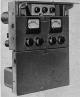
Western Electric and RCA introduced the first commercial peak limiters to hit the market in 1937, WE was first with the 110A, followed six months later by the RCA 96-A
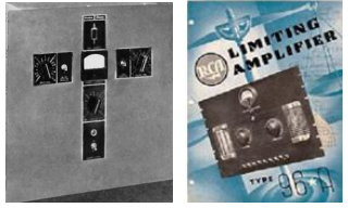
But you could hardly call these boat anchors audio processors. They were basically mundane tools to eliminate over-modulation, pure and 2 simple. Nevertheless, transmitter operators all across the nation gave a huge sigh of relief.
Various engineers immediately saw the potential of having both the hard peak limiter and a softer averaging processor. One of them, Al Towne at KSFO, San Francisco set forth to build what may be the first known actual audio processor: a combined, intelligent compressor (automatic gain control plus a peak limiter).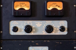
Towne called his idea the PROGAR (PROgram GuARdian), and spent over ten years working on it, getting his design to patent, and selling it to Langevin, which then brought it to market as the PROGAR 119A.
The PROGAR brought automatic gain control and peaking limiting together.
Delaying the Peaks
In the early 40’s, something really exciting happened in the processing world: peak limiting became much more sophisticated.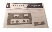
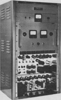
When General Electric finally introduced the BA-5 delay-line peak limiter in 1947, it took the broadcast industry by storm.
Its feed-forward limiting scheme used a delay line to “give the audio a chance to catch up to the bias generator.” Anyone with a processsing background would have to agree that it was ahead of its time – to the extent that it would take decades before another product would match its key feature.
The result was cleaner audio than anything that had come before.
Repainting the Box
How clean was the BA-5?
Back in those days, NBC had an iron-clad rule to use only equipment manufactured by parent company RCA. Yet, even NBC bought BA-5s – removing any evidence of it being a GE product by repainting them in the “standard RCA umber gray” – and adding the RCA meatball.
Magically, the new “RCA Peak Limiter” was born! Very rapidly, every NBC Owned & Operated radio stations began sounding much better thanks to the “midnight engineering.”
Improving the Technology
Meanwhile, GE was already at work on the next step.
Research and innovation helped them continue their dominance of the peak limiter market with the introduction of the BA-6 in the early 1950s and the BA-7 in 1957. These boxes were truly unique. To summarize why these limiters were so good is easy: GE used the input audio to modulate an RF carrier – and then all peak limiting was applied to this carrier. After demodulation, the audio was fed to the transmitter.
Many processing artifacts were eliminated by 3 this scheme, but like many of the early processsors, it was an absolute bear to keep in alignment – and it took two engineers or one bodybuilder to wrestle one of the processors into a rack!
Differing Attitudes
Ironically, throughout the 1950s, while the big AM stations were getting louder and louder, many FM stations eschewed audio processing entirely. I even remember one old-timer studio operator telling me that “you really couldn’t overmodulate the FM.”
As time went on, some FM stations began to install a Fairchild Conax pre-emphasized clipper to tame the pre-emphasis. But that was about it. In fact, it was not at all unusual in those days to watch the modulation monitor “pin” on muted trumpets even when using a (conventional) peak limiter. There was quite a way yet to go in developing effective FM processors.
This divergent attitude toward processors was to continue for a while. As important as a good limiter was in preventing overmodulation, the focus of the audio processing developers was to make the station louder.
Building Effective Compressors
For them, the most important part of a compressor or peak limiter was the gain-control element.
During the early years, this function was usually performed by a tube. The PROGAR used a 6L7 heptode tube.
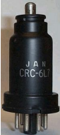 The 6L7 was designed as a variable mu (amplification) tube, which was the purpose of the extra grid.
It came in a metallic can style or the 6L7G glass envelope
At the time, all tube compressors and limiters of the time functioned by mixing a DC control voltage with the audio at the grid of a variable mu tube.
These amplifiers used push-pull operation so the control voltage could be effectively canceled at the output. This reduced the “thumps” that were common when these boxes got out of balance due to tube aging.
The Level Devil
The Gates Level Devil (M5546A) added a leveldependent expansion gate that could release about 10 dB of expansion when the input level was above “noise level.”
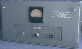
Unfortunately, this gate did not work very well and resulted in a lot of “sucking and wheezing.” However, those were the humble roots of intelligent audio processing.
Jim Tonne recalls the Level Devil “… used a pair of 6BA6s. The expander sounded poor because it was reverse-acting. You had to reach an input level corresponding to 10 dB of compression before the expander would open up – at which time you suddenly had 10 dB of compression. If it would have been forward acting it would have sounded much better.”
The 6386 Rules!
A few remote cutoff tubes were designed before the GE-6386, but this tube became the rock star of the 50s in audio processing.
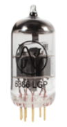
triode tube
The 6386 was a remote cutoff dual-triode, which made it ideally suited to push-pull gaincontrol operation. A remotecutoff tube has a grid wound in a nonlinear fashion and this gives the tube the unique characteristic of reducing its mu with increased osignal levels. A 6386 dual- triode tube
This was a valuable characteristic in a compressor or limiter. Conventional sharp-cutoff tubes tended to operate with substantially more distortion and artifacts.
The 6386 was the basis of the GE Uni-Level limiter, as well as the Gates Sta-Level and CBS’ Audimax compressors
The Sta-Level
The Gates Sta-Level was a straightforward compressor (no limiter), using the 6386 as a gain control element.
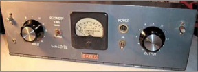 The Gates Sta-Level, a solid performer, was a common sight in stations well into the 1970s.
A 6AL5 dual-diode was used to rectify a sample of the output from a pair of 6V6 tubes operating push-pull. This DC control voltage was fed, via an R/C time constant network to the grids of the 6386 tube.
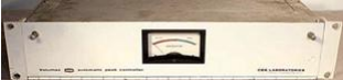
A Clever Marketing Scheme CBS
Laboratories introduced the Audimax I in 1959.
Designed by Emil Torick – and marketed specifically as a “gain rider,” or compressor – the Audimax I made no pretense to being an “audio processor.” Yet, it was the unique design of the Audimax – and its marketing plan – that ushered in the era of audio processing.
The Audimax I was the first broadcast audio processor to be sold on a 30-day trial basis. A broadcaster could submit a purchase order for a unit and put it on the air for a month. If they were not happy with the sound they could return it at the end of the trial period with no questions asked.
The original price for an Audimax was something around a kilobuck (in 1959 dollars). While I am sure CBS got a few of the Audimax’s back, there was no doubt most of those who gave it a try became true believers in the Audimax concept – and the vast majority of users were quite satisfied with this box.
Intelligent Features
Like the Uni-Level and Sta-Level, the Audimax used the 6386 dual-triode to control the audio gain, but some enhancements were made.
For example, a “platform mode” kept the Audimax gain constant over a 6 dB gain platform. This resulted in a lot less “busy-ness” in the sound. When the input audio moved outside the current platform range, the system gain was quickly readjusted to define a new platform.
The Audimax II version quickly followed, adding an adjustable noise gate that froze the gain when input level fell below a user adjusted threshold.
The next model in the line was the Audimax IIRZ, which featured a “return to zero” function that did exactly what you might think: when the input audio was below the threshold of the gate, it slowly returned the system gain to zero.
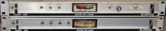
The Maxx Brothers
The Audimax really started the era of aggressive processing. Over the years, it transitioned into solid-state versions, and later added a biaseddiode peak limiter called the Volumax.
The development of the Volumax was indeed a mega-event in the history of broadcast audio processing. Together, the “Maxx Brothers,” Audimax & Volumax, ruled for a decade – and continued to be in demand for another ten years after that! Truly a remarkable record.
There were several modifications applied by engineers who just could not accept the parameters that were fixed in the units. Most of these were attempts to speed up the release action, but there were many others. It seemed like every creative engineer had his own set of Audimax and Volumax tweaks.
In its later years, Thompsen acquired the line and produced a thin, one rack-unit version each of the Audimax and Volumax.
A New, Systematic Approach
In the early 1960s, General Electric and CBS Laboratories basically ruled the roost when it came to state-of-the-art audio processing.
But their success spurred the imaginations of many engineers who thought they could see a better way to create a distinctive sound on the radio. Among them was George Frese, a consulting engineer in Washington State.
Frese was active in doing the yearly Equipment Performance Measurements mandated by the FCC, eventually running some 50 EPMs each year. This gave him an opportunity to analyze many different stations with their varied combinations of transmitters and audio processing. Additionally his work as a 1st Violin, 2nd Chair in a symphonic orchestra gave him a experience with clean audio and how things should sound.
From all this Frese began to see clearly what were the limitations in the audio and transmission system and how they could be overcome by properly designed processors. His work – giving attention to the entire audio and transmission chain – would soon change the whole concept of “loud” – and sell a lot of replacement transformers.
Asymmetry as the Difference
Frese was inspired by the request of a client – a 5 kW station – to explain why a 250 Watt station in the same small market sounded better and noticeably louder than they did.
Both stations were basically fully modulated. However, after looking through and analyzing the audio chain at the 250 Watt station, Frese realized how important it was to have both good frequency response and correct audio symmetry. Lack of either would rob a station of loudness.
Although a few engineers had already noticed the natural asymmetry of the human voice, most 6 did not know how to take advantage of it. Often station audio could be seen as a mixture of waveforms with the highest peaks on the negative side, forcing the processors of the time to react to the wrong peak.
That, Frese decided, robbed stations of signifycant potential audio power.
Solving the Puzzle
One popular approach at the time was to use products like the Kahn SymmetraPeak to create an effect not unlike a long phone line, which tended to average out the positive and negative peaks and bring them close in level.
That solution worked to an extent, but in making most audio symmetrical, it lost the potential advantage of positive peak modulation.
Adding devices that artificially increased positive modulation did increase peaks to a degree, but also usually introduced audible distortion. A different solution, automatic phase flippers to keep the highest peak going positive, usually caused audible problems, too.
Over time, Frese developed a list of nine things that would make a station sound better. Each of these aspects made only incremental .5 to 1 dB differences, but all together they would make a station stand out on the dial. These nine improvements came to be the key features of the processor he would build: The Audio Pilot.
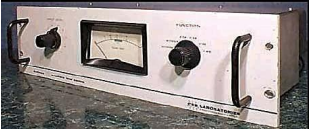
The Frese Audio Pilot
According to Frese, the Audio Pilot got its name from the original design.
At first there were two signal channels, the audio channel and a “pilot” (or, control) channel. The plan was to use an audio delay line so the pilot channel could detect and control the audio peaks without excessive clipping.
However, Frese found that “the audio delay line wrecked the symmetry.” He modified his design to use only one audio path, controlled by the processing system. The product name remained.
The result was an audio processor that was instantly recognizable as soon as someone tuned past it. In fact, when operating on a transmitter with sufficient modulation capacity, a station running the Audio Pilot was LOUD! – hitting 200% without sounding bad! 250 Watt stations out-rocked the bigger 5, 10, even 50 kW rigs.
You can be certain that got the attention of engineers, program direct-ors, station managers, and the FCC. Eventually, pressure from stations not using the Audio Pilot let to the imposition of a +125% maximum for AM modulation.
A Distinctive Selling Strategy
Frese also had a unique sales technique.
He did not just send the processors out to stations. “My procedure was to go to the stations and make the installation myself at no charge to the customer,” Frese said.
By doing the installs himself, he ensured each of his nine points was checked, so the audio would be as clean as possible before and after the Audio Pilot. Frese noted “… the audio always performed more than I expected by sounding better than what they were using and covered more additional area than even I had expected.”
Once the installation was completed: “Then I would stay in the city one day and let them listen to it. The following day The Question was: ‘do you want me to leave it in, or shall I take it out?’ If I took it out there was no further charge. If they kept it, I asked for $2,500 before I left. I lost just one sale …”
Eventually 40 units were sold.
Frese recalled: “I installed Audio Pilots on just about every make and power of transmitters there were.” They were installed from coast to coast and even in Mexico at the famous XELO, a 150 kW flamethrower across the border from El Paso, TX. “Each Pilot went into a different town … but everywhere I went, I met with surprising success at the results.”

A Distinctive Sound
As with most good products, Frese kept refining the operation. “With each one I installed I experienced something new that I hadn’t known before that they would do,” he said.
When set up, most of the control by the Audio Pilot was on the negative peaks. The processor adjusted modulation by reference to the RF carrier level, letting the positive peaks run through while it held the negatives to 99%. This permitted it to work correctly at any power level, even when the transmitter was cut back significantly for nighttime operation. Similarly, power line fluctuations had no effect on the modulation level.
Amazing for its time, the Audio Pilot was conceived to handle a wide range of input. Frese said: “you could leave the console alone and Audio Pilot would ride gain.” The specification in the brochure and spec sheet is impressive: “Output level is constant with input signal of – 40 dBm to +5 dBm.”
Such control, while maintaining an apparently wide dynamic range, was a hallmark of the way the Audio Pilot’s control circuits handled the audio.
Interestingly, the Audio Pilot did not have the fastest recovery time, but that was on purpose. Rather the custom rate of recovery, even when the dynamic range was virtually 0 dB, gave the listener then impression that there was a much greater dynamic range.
The Floating Clipper
Looking the block diagram shows another key feature to the processor: the “Floating Clipper.”
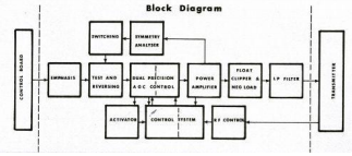 Since the Audio Pilot was designed to enhance positive peaks, it had a clipper designed to automatically adjust to the program level.
The clipper would “float” on the most recent peak, slowly dropping its activation point to the next-highest peak.
When a sudden, higher, sharp peak occurred, the clipper would grab it and clip, instantaneously moving the clip point up-ward so modulation was maximized, protecting the transmitter, yet reducing the need for heavy clipping.
Distortion figures typically were under 1%
– – –
Jim Somich passed away early in 2007 at the age of 65. He was actively interested in audio processing, pushing the envelope at his company, Micro-Com Systems. He also served as Director of Radio Engineering at Malrite Communications, as well as such major stations as KFI, KMET, WMMS, WHK, WHTZ, WJW.
Jim was also very generous with his time, making room to help a number of broadcast engineers to get started.
– – –
The History of Audio Processing will continues with PART 3: MULTIBAND AUDIO
– – –
Are articles like this helpful to you? If so, you are invited to sign up for the one-time-a-week.BDR Newsletter.
It takes only 30 seconds by clicking here.
– – –