

VSWR Calibration Techniques

[September 2014] Among the important ways to keep an FM transmitter happy is to ensure the match to the transmission line and antenna is optimal, as measured by the Voltage Standing Wave Ratio (VSWR). How much VSWR is too much depends upon many factors. That is why you need to make sure your sampling and fold-back trip points are correct and safe. Stephen Rutherford explains:
Over the years, I have gotten calls from clients and some of my engineering brethren because of VSWR trips and/or fold-back activity that were either too sensitive or not sensitive enough for the transmission site. They wanted to know if I knew of a simple way to verify and/or adjust the VSWR trip points.
The simple answer is, Yes, I do, and I will share it with you right here.
The OEM Sampling Unit
First of all, the Forward and Reflected sampling device being discussed in this article is one typically provided by the factory, not the variety manufactured by Bird or Coaxial Dynamics.
Most generally, the OEM sampling device is manufactured by Bendix, Microwave Devices or some other supplier used by the transmitter manufacturer, is silver-soldered to a section of rigid feed-line, and is typically mounted at the output end of the low pass filter assembly.
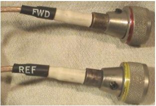
VSWR sample lines. Notice the color banding
The sample output connectors use a threaded collar and have either a red band, for FWD (Forward), or yellow, for REF (Reflected).
Factors That Affect VSWR
Before jumping into tweaking pots and the like, it is imperative to understand the system properly.
The reason for caution is that there may be other factors beside the meter reading to consider before embarking on the process of making any adjustments to the VSWR Calibration, the VSWR trip point, and/or the fold-back settings of an FM transmitter.
For example, it is entirely possible for a VSWR condition to exist within the transmission system and yet there is little or no VSWR indicated. Such VSWR may be present, just physically removed from the sampling point. This situation is caused by the phase signature of the VSWR signal and is a direct result of the antenna load presented to the feed-line and the length of the feed-line between the output of the transmitter and the input to the antenna.
Among other possibilities for misleading meter readings:
- a defective reflected detector diode.
- a coaxial cable from the sampling point to the VSWR control circuitry is open.
- since the samples are not frequency dependent, another FM signal present at the same transmitting facility may be detected by your VSWR sampling device.
In an ideal situation, terminating the transmitter into a proper test load removes the variables that may be presented by the feed-line and antenna combination. On the other hand, when an installation is “less than ideal,” the insertion of a few inches of feed-line is one method to verify the critical phasing of the VSWR signal detection.
Verify the Monitoring System
If it is a transmitting system with which you are not directly familiar, the most important step is to verify the sampling system is properly functioning and no other signals are being presented to the sampling device.
Start by shutting down your transmitter and watch the VSWR indication. If the value drops to zero, then it is more than likely showing your VSWR signal indication and no other.
The VSWR fold-back and trip points are established by the factory during the final tune and test procedures. These settings are based upon specifications for the predicted operational conditions the transmitter is expected to experience as supplied by the original purchaser. Thus, you should have at hand the factory test data for the power level at which your transmitter was originally ordered and tested.
Without further specifications from the original buyer, the factory typically will, for safety reasons, set trip points at a conservative point below the factory-known maximum safe values.
Evaluating VSWR Settings
In my experience there are two conditions when VSWR settings may no longer be appropriate.
The first would be if an uninspired neo-engineer willfully changed the settings because of an adverse situation at the site and he did not wish to be bothered by alarms. The other would be if the transmitter had been purchased, retuned to a new frequency and/or power level, and placed back into service.
In the latter situation, the VSWR protection circuitry may have been overlooked by the rebuilding engineer because the transmitter was operating into a test load.
Either way, it is useful to have a test device that will help you determine, in the field, if the transmitter’s VSWR settings are appropriate.
A VSWR Test Set
I built my own test set a long ago, and since then have loaned it out many times to engineers to resolve VSWR calibration problems. It is extremely simple, easy to build from scratch, and provides a very quick and accurate method to either verify the settings or to calibrate them for the installation.
The device is devilishly clever as it is simple. Here is the whole parts list for my DC Substitution Box:
- a 1.5 VDC battery
- a 10k-Ohm, ten-turn potentiometer
- an SPST switch
- some coaxial cable
- a BNC connector
- a Switchcraft P/N 2501F, high impedance unbalanced microphone connector.
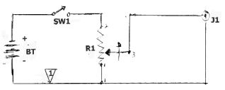
Legend:
R1 = 10 k Ohm, 2%, 10-turn precision potentiometer
BT = 1.5 V DC Battery, Alkaline
J1 = Isolated BNC Jack
Note 1: This portion of the circuit should not be tied to the metallic enclosure or chassis for isolation, but it is not necessary when using a grounded BNC jack.
If you wish to add a DC polarity reversal switch, you will need a second switch, a SPDT unit.
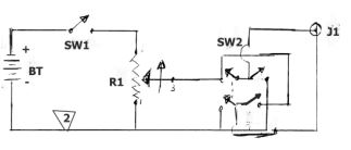
Note 2: Here, an isolated BNC must be used for the application, and this portion of the circuit must not be tied to the metallic enclosure or chassis.
Over the years in the field, I have proven that the accuracy of this simple device is only limited by the accuracy of the RF metering associated with the transmitter.
Building the Test Set
The construction process is very straight forward, and can be more or less elaborate according to your personal tastes.
Nevertheless, if you do consider building this project, I do highly recommend wiring the tenturn potentiometer so that the output of the device is 0 VDC when fully counter-clock-wise.
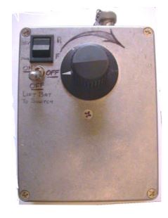
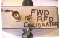
This is a top view of my DC Substitution Box
You will notice the power on/off locking toggle switch, the optional polarity reversal switch, and the knob for the 10-turn potentiometer.
The output connector
The connector is on the end of the box. I used an isolated BNC connector because I incorporated a polarity reversal switch.
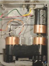
The three “C” batteries were connected in parallel.
You can see here how the batteries were mounted in the enclosure.
The reason for using three cells was to provide longer battery life while the test device was in use.
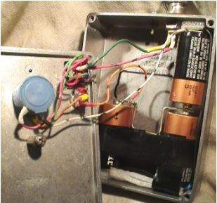
Final Product
Here is how it looks with the cover off, once it is all put together:
For the adaptor, I modified Switchcraft 2501F high impedance, unbalanced microphone connector
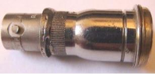
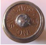 The modification requires one to carefully file off all but the last two threads because the Forward and Reflected sample connectors do not have the same thread pitch.
Actually, without modifying the Switchcraft, the directional couplers will not make electrical connection.
I used my cordless drill and a jeweler’s file for this part of the construction. Removing all but the last two threads will allow the directional coupler connectors to be attached to the adaptor.
Careful Connection
Speaking of the directional coupler connectors; be extremely careful when attaching them to the adaptor or returning them to the directional coupler.
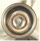
Looking into the end of the connector, you are actually looking at a 500pf RF bypass capacitor that is also sup-porting the center connector.
Excessive tightening will fracture the bypass capacitor and eliminate the RF bypass protection and will cause very erratic meter readings.
By the way, it is not totally necessary to use an isolated BNC jack. Still, I chose to do so for two reasons. First, I incorporated a DC polarity reversal switch in the design and secondly, to isolate the metal box from the equipment to prevent potential RF ground loops.
Operating the Test Set
Operating this Sample Substitution device is pretty simple.
- Turn off or disable the Automatic Power Control and if possible, disable the VSWR Fold Back and VSWR Trip circuits, (how-ever this is not critical).
- Verify the transmitter is producing the authorized RF power output and the RF output meter is indicating 100% forward power. Note the position of the meter pointer.
- Carefully remove the Forward power sampling connector from the directional coupler that supplies the DC sample voltages to the transmitter controller; typically this will be the twist-on collar with the red marking ring. A note or precaution: remember the RF by-pass capacitor – just a word to the wise!
- Connect your DC Substitution device to the Forward power sample cable removed from the directional coupler in step #3.
- Turn on the DC Substitution device and very slowly turn the ten-turn pot clockwise while watching the Forward Power meter on the FM transmitter.
- Precisely set the 100% indication on the Forward Power meter with the DC Substitution Box to match the same indication provided by the transmitter as noted in step #2.
- Without disturbing the potentiometer setting, remove the Forward Power sample cable, restore it to the directional coupler, then remove the Reflected Power sample cable from the directional coupler. Typically this twist-on collar will have a yellow marking ring.
- If possible, switch the transmitter output meter to “VSWR Cal” position, then connect the Reflected Power sample cable to your DC Substitution device. The output meter should now be indicating 100% because the DC Substitution device is supplying a DC voltage equivalent to 100% Forward Output Power. Follow the manufacturer’s maintenance instructions and adjust the transmitter’s VSWR Cal pot to set the calibration point for VSWR. It is important to understand that this VSWR calibration point is not based on a non-inductive 50 Ohm test load; it is based upon the load terminated to the transmitter.
- Next, reduce the DC Substitution device DC output with the ten-turn pot until the transmitter output meter indicates somewhere less than 1.2:1 then switch the transmitter output meter to “VSWR.” Ideally, the transmitter should remain at its full power without VSWR trips or faults.
- Be aware that the transmitter may experience a VSWR shut down during this step. Slowly increase the DC Substitution output by turning the control clockwise while watching for a VSWR Fold Back and/or VSWR Trip indication. If the trip point is less than the anticipated VSWR for your installation, carefully adjust the VSWR Trip control of the transmitter to set the VSWR threshold value for the transmitter.
- Increase the DC substitution device until the transmitter output meter is indicating the desired VSWR Trip point, then readjust the VSWR Trip control of the transmitter until the trip indication just illuminates. For best accuracy, adjust the trip control back and slowly increase the sensitivity a second time.
- If your FM transmitter has VSWR Trip and VSWR Fold Back capabilities, first desensitize the VSWR Fold Back control by raising the threshold to a higher level, then set up the VSWR Trip point following the above procedure. With the Trip point established at the desired maximum VSWR point, reduce the DC Substitution device until the transmitter output meter indicates the desired VSWR Fold Back indication – then adjust the VSWR Fold Back control of the transmitter down to instigate the proper fold-back action.
Always Check the Book First
A final note: Not all transmitter controllers have the same functionality and it is highly recommended that you familiarize yourself with those circuits and controls for your particular transmitter. Then, you will be able to adapt this DC Substitution device to accommodate your maintenance needs.
It is the elegantly simple things in life that are most appreciated and have the greatest effect.
– – –
Stephen Rutherford is a contract engineer based in Lincoln, NE. You can contact him at: twicethefirst@gmail.com