
Understanding AM NRSC Measurements

[January 2013] The FCC requires that AM stations perform their NRSC measurements each year. What do they mean? And how can this measurement be used to improve your station? James Boyd runs it down.
There are still some of us who remember those all-nighters at our AM stations doing the annual Equipment Performance Measurement (EPM), or what we lovingly called the “audio proof.”
The EPM usually involved putting in a new set of modulator tubes – sometimes new finals too – and then turning knobs on the HP distortion analyzer to get the distortion null. At 50 Hertz, near 100% modulation the rig would occasional overload and drop off.
I think most of us rejoiced when the FCC did away with the EPM Rules. Unfortunately, the respite from the annual “proof” did not last very long. New Rules came along which made making the annual measurements more difficult for many station chief engineers.
The Road From EPM to NRSC
The increasingly poor audio response of AM receivers being manufactured triggered some of the change, and the rest was the result of a proliferation of AM stations and the need to minimize first adjacent channel interference at night.
In 1986 the National Radio Systems Committee (NRSC), a joint committee composed of representatives of AM stations, AM receiver manufacturers and broadcast equipment suppliers developed a set of standards employing preemphasis and setting an AM audio bandwidth limit of 10 kHz. Then, early in 1987, the NRSC authorized the Electronic Industries Association (EIA) and the National Association of Broadcasters to publish this set of standards, calling it NRSC-1. Compliance with these NRSC-1 standards was – at that time – voluntary.
NRSC-2 came in June of 1988, when the NRSC released further refined standards, setting forth the emission limitations for AM broadcast stations. In April of 1989, the FCC officially adopted NRSC-2 and subsequently published 73.44, the Rule we live by today.
Quoting section (e) of the Rule, the Commission allowed that “Licensees of stations complying with the ANSI/EIA-549-1988, NRSC-1 AM Preemphasis/Deemphasis and Broadcast Transmissions Bandwidth Specifications (NRSC-1), prior to June 30, 1990 or from the original commencement of operation will, until June 30, 1994, be considered to comply with paragraphs (a) and (b) of this section, absent any reason for the Commission to believe otherwise. Such stations are waived from having to make the periodic measurements required in §73.1590(a)(6) until June 30, 1994.”
Thus, on June 30, 1994, the now annual “NRSC Measurement” was born. It should be noted that the years leading up to NRSC-1, NRSC-2, and the adoption of 73.44, were lively. There was a great deal of controversy about AM transmission and its standards.
Deconstructing 73.44
Let us look at some of Rule Section 73.44 and its requirements. The first paragraph (a) says:
“The emissions of stations in the AM service shall be attenuated in accordance with the requirements specified in paragraph (b) of this section. Emissions shall be measured using properly operated and suitable swept-frequency RF spectrum analyzer using a peak hold duration of 10 minutes, no video filtering, and a 300 Hz resolution bandwidth, except that a wider resolution bandwidth may be employed above 11.5 kHz to detect transient emissions. Alternatively, other specialized receivers or monitors with appropriate characteristics may be used to determine compliance with the provisions of this section, provided that any disputes over measurement accuracy are resolved in favor of measurements obtained by using a calibrated spectrum analyzer adjusted as set forth above.”
It is pretty clear that you can use other measuring methods and equipment than a spectrum analyzer for determining compliance with 73.44. But disputes must be resolved by the use of a spectrum analyzer.
It is my opinion that the spectrum analyzer is the most accurate way to make compliance measurements.
Paragraph (a) details the technical “how to” for the spectrum analyzer setup. Paragraph (d) describes the “where,” the location at which the measurements should be taken.
We know the antenna system affects the bandwidth of our AM signal and hence it can modify the emission limitation characteristics of our audio processing and our transmitter. That is why we head into the field to make our NRSC measurements.
Setting Up For NRSC
Here is what paragraph (d) says:
“Measurements to determine compliance with this section for transmitter type acceptance are to be made using signals sampled at the output terminals of the transmitter when operating into an artificial antenna of substantially zero reactance. Measurements made of the emissions of an operating station are to be made at ground level approximately 1 kilometer from the center of the antenna system. When a directional antenna is used, the carrier frequency reference field strength to be used in order of preference shall be:
(1) The measured non-directional field strength.
(2) The RMS field strength determined from the measured directional radiation pattern.
(3) The calculated field strength that would be expected to radiated by a nondirectional antenna at the station’s authorized power.
As a practical matter, the 1 kilometer distance from the center of the antenna system might be changed a bit by the engineer making these annual measurements.
The exact location of the selected measurement point may depend on the power of the station, accessibility of the measurement location and other issues such as overhead power lines or other structures which could modify the field strength at the desired location.
The NRSC RF Mask
Finally, we come to the heart of the Rule: the “RF Mask.” This is the definition of the amplitude limits of the signals coming from the station in terms of frequency away from the carrier. Here is what the Rule says in paragraph (b):
(b) Emissions 10.2 kHz to 20 kHz removed from the carrier must be attenuated at least 25 dB below the unmodulated carrier level, emissions 20 kHz to 30 kHz removed from the carrier must be attenuated at least 35 dB below the unmodulated carrier level, emissions 30 kHz to 60 kHz removed from the carrier must be attenuated at least [5 + 1 dB/kHz] below the unmodulated carrier level, and emissions between 60 kHz and 75 kHz of the carrier frequency must be attenuated at least 65 dB below the unmodulated carrier level. Emissions removed by more than 75 kHz must be attenuated at least 43 + 10 Log (Power in Watts) or 80 dB below the unmodulated carrier level, whichever is the lesser attenuation, except for transmitters having power less than 158 Watts, where the attenuation must be at least 65 dB below carrier level.
Here is what the NRSC RF Mask “looks like” in an amplitude versus frequency graph:
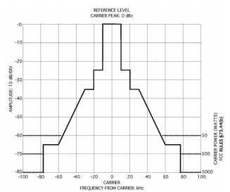
Analog AM Broadcast RF Emission Limits
(These graphs are courtesy of the NRSC as published in NRSC-2-A.)
Next, we will focus in on the area close to the on-channel carrier itself. This expanded scale will bring us to +/- 25 kHz from the carrier.
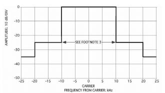
Analog AM Broadcast RF Emission Limits (Expanded Scale)
Overall, these limits are not very stringent. Some might draw the conclusion that with modern transmitters and processing, there is little need to worry about whether the station emissions are “in the “mask.” But modern transmitters that are not running right can cause several problems.
Why Do We Measure Every Year?
Speaking of common problems, the most common problem is consistent overmodulation on negative peaks.
Of course 100% negative modulation is not lawful, but it happens. And when it does – when the carrier “pinches” off – a lot of splatter occurs above and below the normal sidebands. More often than not, such splatter rises above the mask.
For the most part today, our audio processors handle most of the work to keep RF emissions within the NRSC RF Mask. However, when things go wrong in a transmitter or antenna system, the emission picture can change radically. And this is one of the reasons the FCC requires these measure-ments to be made annually.
For example: when MOSFETs fail in the final amplifier stage of the transmitter, they can go unnoticed for some time. The transmitter continues (in most cases) to make full or near full power, but the audio harmonic distortion can rise dramatically, producing splatter that rises above the mask. PDM modulated rigs can have symmetrical spurs at the PDM frequency above the mask if something is wrong with the PDM filters. And it happens more often than you may think.
The Intermod Factor
Another challenge that crops up occasionally is intermodulation. If there is another AM station within a few miles of your facility you can be susceptible to intermodulation. Interestingly, modern solid state rigs exhibit the problem more than older tube rigs.
The most common form happens when the other station’s signal manages to get back to your transmitter’s final amplifier where it mixes with the second harmonic present in the PA stage. What comes out is two times your frequency minus the other transmitter’s fundamental, or intermod.
For example if you are on 1240 kHz and there is a station on 1410 kHz located a few miles away, an unwanted intermod signal may appear on 1070 kHz. Another signal result from this kind of mix could be on 3980 kHz.
Making Sure About Intermod
A Potomac Instruments FIM-41 is commonly used to track down these problem mixes. You might hear such a mix on your car radio, but always double-check with the FIM. The reason is that car radios can – and do – generate these kinds of products on their own when in fact they may not actually be transmitted.
If the offending signal mix is less than 43 + 10 X Log of the station power in Watts or 80 dB (whichever attenuation is less) below the unmodulated carrier level, steps must be taken to suppress the product to this level or greater.
This usually involves designing and installing a notch filter to remove the station before it gets to the transmitter.
The Actual NRSC Measurement
Let us conclude our discussion with a brief “how to” make the NRSC measurements. Even if you do not do this yourself, it will help you to understand the report and what it means.
First, the station pattern is checked; if the station is a directional the shape of the pattern is checked (this data usually shows up on the FCC AM Query database). A site is chosen in the main lobe of the station at a distance of about 1 kilometer from the antenna site. The location chosen should be away from power lines.
Next the NRSC test antenna is setup and pointed toward the station. For the best accuracy, reducing radiation from adjacent stations, it is desirable to use a shielded loop antenna.
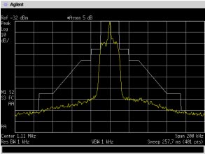
After the spectrum analyzer has been turned on and stabilized, a measurement with a frequency span of 200 kHz and a resolution bandwidth of 1 or 3 kHz or is made. The instrument is set for peak hold, so that the highest peaks in the measured band during the test period can be easily seen. After collecting the data for 10 minutes, the display is checked to see if it is in the mask. If the station is in the mask, the data is saved for importing into a written report later.
As an example, here is one such display.
Looking More Closely
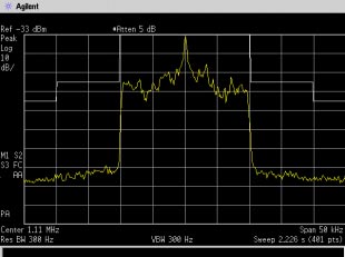
Next, the span is reduced to 50 kHz and the resolution bandwidth is set to 300 Hertz. Again, with the peak hold feature on, the data is collected for ten minutes and then saved for the report. As noted earlier, these two plots are detailed in paragraph (a) of the FCC Rule.
If the station has more than one mode of operation, for example non-directional daytime and directional at night, measurements are made for the other modes of operation. In some cases, such as when there is a directional pattern day and night but different parameters, it may be necessary to find another measurement location for the other mode of operation.
Beyond the Spectrum Analyzer
I use a Potomac Instruments FIM-41 to look at the spectrum from 540 kHz to 5.0 MHz and checking signals to see if they are related, either harmonically or by intermodulation, to the station being measured.
Any signal discovered which is related is carefully measured with the FIM and compared to the FIM reading of the station fundamental frequency. During such measurements, it is important to have the FIM aligned toward the station antenna array. Occasionally, harmonics may be generated by nearby power lines or other re-radiating sources.
In a nutshell, this is the process for these annual measurements – required annually by definition in FCC Rule 73.1590. While it can be some rather dry reading, Section 73.1590 and Section 73.44 are printed below for your reference. They are good things to know to stay in compliance with the Rules and to avoid heavy fines.
– – –
We are saddened to report James Boyd passed away on May 20, 2022. But his knowledge and willingness to share remains, as exemplefied in this article.
– – –
Reference information:
§73.1590 Equipment performance measurements.
(a) The licensee of each AM, FM, TV and Class A TV station, except licensees of Class D non-commercial educational FM stations authorized to operate with 10 watts or less output power, must make equipment performance measurements for each main transmitter as follows:
- (1) Upon initial installation of a new or replacement main transmitter.
- (2) Upon modification of an existing transmitter made under the provisions of §73.1690, Modification of transmission systems, and specified therein.
- (3) Installation of AM stereophonic transmission equipment pursuant to §73.128.
- (4) Installation of FM subcarrier or stereophonic transmission equipment pursuant to §§73.295, 73.297, 73.593 or 73.597.
- (5) Installation of TV stereophonic or subcarrier transmission equipment pursuant to §§73.669 and 73.1690.
- (6) Annually, for AM stations, with not more than 14 months between measurements.
- (7) When required by other provisions of the rules or the station license.
(b) Measurements for spurious and harmonic emissions must be made to show compliance with the transmission system requirements of §73.44 for AM stations, §73.317 for FM stations and §73.687 for TV stations. Measurements must be made under all conditions of modulation expected to be encountered by the station whether transmitting monophonic or stereophonic programs or providing subsidiary communications services.
(c) TV visual equipment performance measurements must be made with the equipment adjusted for normal program operation at the transmitter antenna sampling port to yield the following information:
- (1) Field strength or voltage of the lower sideband for a modulating frequency of 1.25 MHz or greater, (including 3.58 MHz for color), and of the upper sideband for a modulating frequency of 4.75 MHz or greater.
- (2) Data showing that the waveform of the transmitted signal conforms to that specified by the standards for TV transmissions.
- (3) Photographs of a test pattern taken from a receiver or monitor connected to the transmitter output.
- (4) Data showing envelope delay characteristics of the radiated signal.
- (5) Data showing the attenuation of spurious and harmonic radiation, if, after type acceptance, any changes have been made in the transmitter or associated equipment (filters, multiplexer, etc.) which could cause changes in its radiation products.
(d) The data required by paragraphs (b) and (c) of this section, together with a description of the equipment and procedure used in making the measurements, signed and dated by the qualified person(s) making the measurements, must be kept on file at the transmitter or remote control point for a period of 2 years, and on request must be made available during that time to duly authorized representatives of the
FCC. §73.44 Emission limitations.
(a) The emissions of stations in the AM service shall be attenuated in accordance with the requirements specified in paragraph (b) of this section. Emissions shall be measured using properly operated and suitable swept-frequency RF spectrum analyzer using a peak hold duration of 10 minutes, no video filtering, and a 300 Hz resolution bandwidth, except that a wider resolution bandwidth may be employed above 11.5 kHz to detect transient emissions. Alternatively, other specialized receivers or monitors with appropriate characteristics may be used to determine compliance with the provisions of this section, provided that any disputes over measurement accuracy are resolved in favor of measurements obtained by using a calibrated spectrum analyzer adjusted as set forth above.
(b) Emissions 10.2 kHz to 20 kHz removed from the carrier must be attenuated at least 25 dB below the unmodulated carrier level, emissions 20 kHz to 30 kHz removed from the carrier must be attenuated at least 35 dB below the unmodulated carrier level, emissions 30 kHz to 60 kHz removed from the carrier must be attenuated at least [5 + 1 dB/kHz] below the unmodulated carrier level, and emissions between 60 kHz and 75 kHz of the carrier frequency must be attenuated at least 65 dB below the unmodulated carrier level. Emissions removed by more than 75 kHz must be attenuated at least 43 + 10 Log (Power in watts) or 80 dB below the unmodulated carrier level, whichever is the lesser attenuation, except for transmitters having power less than 158 watts, where the attenuation must be at least 65 dB below carrier level.
(c) Should harmful interference be caused to the reception of other broadcast or nonbroadcast stations by out of band emissions, the licensee may be directed to achieve a greater degree of attenuation than specified in paragraphs (a) and (b) of this section.
(d) Measurements to determine compliance with this section for transmitter type acceptance are to be made using signals sampled at the output terminals of the transmitter when operating into an artificial antenna of substantially zero reactance. Measurements made of the emissions of an operating station are to be made at ground level approximately 1 kilometer from the center of the antenna system. When a directional antenna is used, the carrier frequency reference field strength to be used in order of preference shall be:
- (1) The measured nondirectional field strength.
- (2) The RMS field strength determined from the measured directional radiation pattern.
- (3) The calculated expected field strength that would be radiated by a nondirectional antenna at the station authorized power.
(e) Licensees of stations complying with the ANSI/EIA-549-1988, NRSC-1 AM Preemphasis/Deemphasis and Broadcast Transmissions Bandwidth Specifications (NRSC-1), prior to June 30, 1990, or from the original commencement of operation will, until June 30, 1994, be considered to comply with paragraphs (a) and (b) of this section, absent any reason for the Commission to believe otherwise. Such stations are waived from having to make the periodic measurements required in §73.1590(a)(6) until June 30, 1994. However, licensees must make measurements to determine compliance with paragraphs (a) and (b) of this section upon receipt of an Official Notice of Violation or a Notice of Apparent Liability alleging noncompliance with those provisions, or upon specific request by the Commission.