

The Nautel J-1000

[August/September 2009] Replacing a new transmitter can be major undertaking, especially when it uncovers some of the shortcomings of the original installation. Years ago, it might take days or weeks to get everything right – from electrical and coax connections to the transmission line matching. Today’s models are a magnitude easier to install. For example, Scott Cason recalls his experiences with the Nautel J-1000.
I have had the pleasure of installing three of Nautel’s J-1000 transmitters and would like to share with you my installation experience with latest one.
As the contract engineer for this particular client, in Louisville, Kentucky, since 2001, I had been maintaining their aging Harris SX 2.5 main transmitter (with a CCA 1000D for a backup). When Harris stopped support of the SX line in April of 2008, the company’s Director of Engineering realized it was time to replace our aging rig.
Ready to Install
The transmitter arrived on a Tuesday afternoon. Fully crated, including the rack, the total weight was 320 lbs. While that is maneuverable with just one person, I highly recommend getting a second pair of hands.
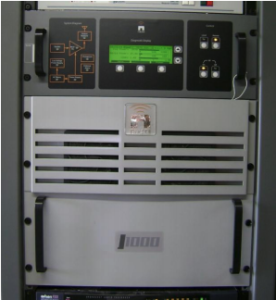
Delivery, setup and installation were the easiest of any installation I can remember. In my previous J1000 installations, we used space available in existing racks. This time the transmitter was ordered already mounted and wired up in the matching rack option. We uncrated it and placed it where the CCA had sat next to the Harris.
Ordering the rack from Nautel allowed me to move equipment out of an older rack where the holes were not quite aligned and keep as much of the equipment centralized as possible. In fact, the only thing left in the old rack is the antenna monitor and antenna controller.
Hooking Up the Power Input
Once in place, the wiring began. Since the CCA is gone, the AC circuit it used was put in service for the J-1000’s exciter and two 500-Watt power amplifiers. It was during this step that I run across my only problem with the J-1000.
The Nautel guide recommends to using 10-gauge wire for the incoming power. However, once the shells are placed around the wire and screwed together on the connectors for the exciter and power amplifier assemblies the connectors that Nautel supplies are hardly able to contain the 10-gauge wire. I would recommend the connectors be made slightly larger to accommodate the larger wire.
By the way, Nautel has, as an option, a surge suppressor for the incoming AC, outgoing RF and remote lines. I highly urge this surge suppressor be ordered as part of the transmitter package.
Here is why: The owner of one station where I installed a J-1000 in 2007 decided to cut corners and not order the surge suppressor. After the first lightning strike, the cost in parts and labor would have more than covered the surge suppressor. Indeed, at other transmitter sites I maintain in and around Louisville with Nautel transmitters, I credit the surge suppressor for preventing major down time.
Ignition
Once the AC lines were in place, the RF output was hooked up. The RF output of the surge suppressor assembly has interchangeable connectors; you can select between N connectors, stud connectors, or a 7/8-inch flange connector for the outputs. The CCA had a stud output, and since the half-inch Heliax still had the stud connector on it, I elected to go with the stud as the output connector on the surge suppressor.
When the RF hookups were completed, the all important smoke test was next. Power was applied to the box and it jumped to life with no errors on the front display (and no sparks from the AC connectors). Finally it was time to turn on the RF.
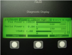
After pressing the RF ON button on front of the exciter, the fans on the power amplifiers spun up and B+ voltage came up – but there was no current or power output. At first, I started to panic, thinking something was wrong. But it was I that was wrong; until you tell the transmitter what power you want, it just waits for you.
Once I programmed one preset with our daytime power of 1000 Watts and another with our night time power of 500 Watts, everything was fine.
Actually, Nautel supplies the J series with six power presets and a power preset scheduler, which gives additional flexibility. For example, our antenna also has the option of going non-directional. With that in mind; I programmed the a fourth preset for 100 Watts, just in case we ever need to operate nondirectionally.
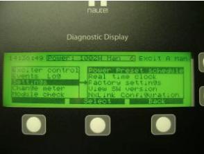
The power preset scheduler is handy if you are non-directional or if you run the same antenna pattern day and night. Since we also have to change patterns along with power from day to night, I decided to allow the Burk AutoPilot to control power levels on the transmitter along with changing our day/night patterns and did not program the Nautel’s power scheduler.
The transmitter was allowed run at a thousand Watts for 10 minutes. Then it was shut down and I checked all the AC and RF connectors. Nothing was unusually warm so I moved on to hooking up remote control and audio.
Rack Mount
Once the transmitter was verified to be functioning properly, the next thing was to start moving the equipment.
As mentioned earlier, the rack we had been using to hold equipment like the Burk ARC-16, ABC Radio network satellite receiver, and the Harris Interplex was not the most desirable rack. In fact, I think it must have been dug out of a trash dump or something. The holes for mounting equipment into the rack were misaligned. This made for a lot of wasted space.
Instead, ordering the rack-mounted option with the Nautel allowed me enough room to move everything but the antenna monitor and antenna controller closer to the new transmitter. This also cut down on wiring runs since the remote control and satellite receiver are all in the same rack with the transmitter.
Hooking Up the Control and Audio
First to be moved was the remote control. Remote control hookups, along with interlock and audio, for the Nautel are very easy to access since they are on a screw terminal block on the back of the exciter assembly. Practically everything can be monitored on the remote control outputs.
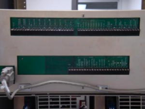
As I said, the remote control hookups were very easy. They are all clearly labeled, screw terminal connections on the back of the exciter assembly. Using the transmitter’s internal 24-Volt power supply, control channels are a simple contact closure to ground. Status outputs and alarms use a sink to ground connection when the output is active. Using the 24-Volt power supply keeps everything internal and no external power supplies or relays are needed. The remote control we use is happy with both of these interfaces.
The audio was a simple 600-Ohm connection from our processor output to the audio input on the back of the exciter.
Power to the Tower
With everything hooked up now, the transmitter was turned back on and fed into the dummy load where modulation levels were checked. With modulation set properly, a press of the “main” button on the antenna controller then fed the new Nautel into the phasor and antenna, putting it on the air.
The total time from uncrating until on the air was two days but this only was because I was not in a hurry and could take time. I had a J-1000 on the air in six hours at a previous client when their 40-yearold main transmitter failed and parts would have taken too long to arrive.
Communicating With the Transmitter
However, the really neat part is the Ethernet interface for monitoring the transmitter.
The Ethernet interface allows for two valuable functions. First, you can remotely access the transmitter and see all measured voltages, status indications and RF health. Secondly, the transmitter can send emails when a fault occurs. (You can configure when the transmitter emails and how much information is sent out in the email.)
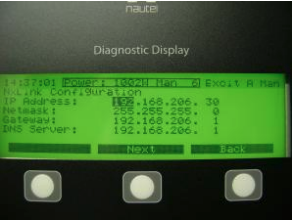
Currently, I have the transmitter emailing me when the external interlock opens indicating a pattern change. However it can also email me with any fault that takes it off the air or reduces the power. I can receive these emails on my Blackberry and then determine if I need to drop what I am doing, switch transmitters, and head to the site. If the problem does not demand an immediate response, I can schedule time to go by the transmitter site.
N+1 Or Just 1
Nautel has a frequency change kit option that when used with the J-1000 will allow it to be used as a standby for several different stations. One J-1000 could serve as a standby transmitter for several co-owned AM stations in a market or region.
After three installs, I can report being very happy with the results. Nautel has built a solid, reliable transmitter with the J-1000. This is a transmitter I would not hesitate to recommend to other station owners wanting to replace older, less efficient transmitters, or simply wanting to keep up with the latest in transmission technology.
– – –
Scott Cason is a contract engineer based in Louisville, KY. You can contact him at scott@lagrangecommunications.com