

Omnia Turns it Up to 11
[May 2011] Having a backstage pass can be a really cool experience. No matter what the event or venue, you are able to get a glimpse of what it takes behind the scenes to put on something spectacular. This also is true with an audio processor, as there is a lot going on “backstage‟ to offer up that larger-than life sound that is the star of the show. Here is a peek behind the curtins of the Omnia.11.
The ultimate goal for any station is to make its audio “jump” out of the radio, with a sound that makes the listener notice and stay with the station. Audio processors are the key tool for achieving that goal.
Aside from all the auto-magical algorithms inside, Omnia.11 revolves around a few key principles that are the core to its effortless competitive signature.
The magic inside Omnia.11 can be easily described as follows: get the levels right – all the time – and create the smoothest peak control for both dynamic and hard limiting. Two functions sum it all up, smart RMS level control, and maintaining intermodulation distortion (IMD) at a minimum.
Sounds simple right?
Well, let us contemplate this quote from Malcolm Gladwell’s book Outliers, “it takes 10,000 hours, or more, to excel at something.” Considering all the audio processors that preceded Omnia.11 – some of which were our own – this seems to prove Mr. Gladwell is correct. Achieving smart RMS level control and low IMD has taken the better part of two processing careers: that of my cohort in crime Cornelius Gould, and that of yours truly.
Don’t Touch It! Don’t Even Look at it!
Clearly, what sounds simple may well involve a much more complex set of efforts than merely cranking up the output knob.
Nigel Tufnel was a bit over the top when asked about one of his guitars in the hilarious movie “Spinal Tap.” His response, while demonstrating the controls on one his amplifiers, was “The numbers all go to 11.” Indeed, Tufnel’s amplifier had control knobs labeled from 0 to 11 (instead of the normal 0 to 10 markings), in the belief that just turning it up to 11 made it louder.
Nigel’s revelation about “these go to 11” can be viewed as a premonition for broadcast audio processsing, as many radio stations are on a quest to get to 11!
Getting the Levels Right – All the Time!
Theories abound about how to create perceived loudness. The trick is how to achieve this, yet minimize the annoyance and distortion commonly associated with competitive processing.
In general, audio processors funnel wide dynamic range audio down to the precision peak-controlled signal needed for transmission. This is accomplished through a series of processing functions such as compression, limiting, and distortion-managed clipping. Each provides its own function in order to obtain maximum sonic benefit.
Simply stated, the compressor (least aggressive sounding) feeds a peak limiter (more aggressive sounding), and then the distortion-managed clipper, which is the most aggressive element.
A Bump in the Processing Roadway
Common practice has been to utilize the limiter and clipper for creating loudness, and the AGC to balance the spectrum. While this does work, it brings along associated intermodulation (IMD) distortion, which results in sonic annoyance to the listener.
Recent efforts to reduce, and in some cases eliminate IMD have improved processing systems, but that is not the ultimate answer. Even though lowering IMD helps, limiters and clippers are still aggressive sounding, no matter what.
The secret to generating consistent and pleasing competitive loudness is to be found in the AGC or compressor section. This is not novel or new. What is novel is how this section in the Omnia.11 generates its internal control signal that enables consistent sounding and non-aggressive audio.
Hearing the RMS
Research shows the human ear is an RMS (root means square) detector. This is how we judge the loudness of one signal to another. The ear basically ignores a change in short-term peak level, locking onto changes in the average level over a period of time.
In contrast, the limiters employed in broadcast processors are peak responding, and react over a much shorter duration. In order to increase the RMS level through limiting means, we need to drive more limiting to increase the perceived RMS level. This is counter-productive, as considerable amounts of limiting are required. While the RMS level will eventually increase, so will the perceived level of IMD, and this is where processing artifacts are generated.
Affecting a change in RMS level is done in the AGC/compressor section. RMS based compressors are not new. They have been deployed before and, based upon how the detector operates, they had a few sonic challenges to overcome – until now!
RMS in the Processor
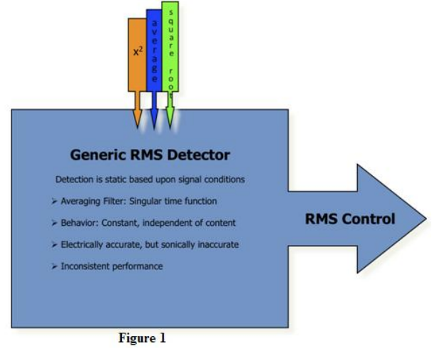
In prior implementations, the difficulties were based upon the single time constant used to calculate the RMS level. This works great when measuring steady state signals.
Audio signals, on the other hand, cover a wide range of spectra, and the averaging function of the RMS detector is not consistent in level detection over this wider range. The result is inconsistent level control, as well as occurrences where the audio signal will sound abnormally weak, and usually non-musical.
This problem can be minimized through the use of multiband AGC/compression, but it still occurs. Actually, in the multiband case a new and additional problem arises.
When RMS detection errors occur, they now affect the sonic level, as well as the tonal balance of the spectrum.
The result is a combination of incorrect levels and EQ, which is very nonmusical and a double negative. Figure1 offers an overview how the basic RMS function operates.
All is not lost however. The magic lies in the RMS detector. As mentioned earlier, a single averaging function is used.
New developments, where the averaging function is performed through analysis of the signal’s incoming density, and rate of level change, allow the RMS detection to be accomplished in a natural and musical manner.
All levels are adjusted properly across the audio spectrum. This enables the AGC function to operate in either a wideband or multiband configuration.
When used in the multiband mode, the resultant spectrum is consistent in level and frequency balance.
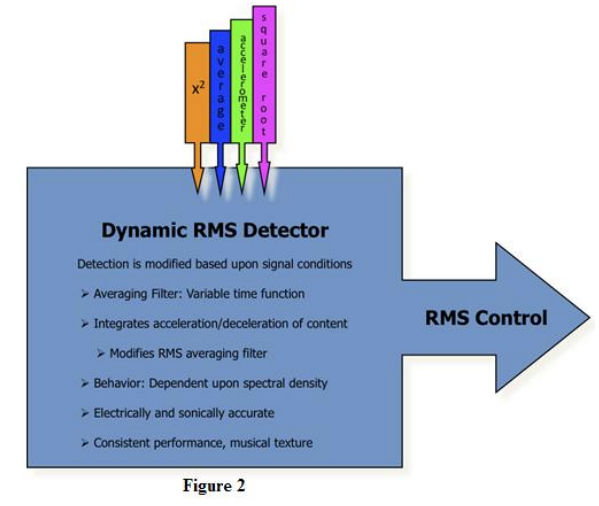
Figure 2 illustrates this model.
Why is this so important? Now, the mechanism is in place to set RMS (loudness sensitivity) levels to where they need to be, and keep them there. Also, spectral balance is achieved consistently over a broad range of content – music, live speech, commercials, station sweepers, etc.
Now, here is the added benefit: since the less aggressive sounding sections – the Wideband-AGC and multiband compressors – have set the RMS (loudness) levels and EQ to the desired target range correctly, the following peak limiters and distortion-managed clippers are then set for moderate operation. This yields less activity in the multiband limiter (reduced IMD), and the desired amount of distortionmanaged clipping is consistent at all times!
Managing the Bands
This sheds some light on another misnomer about processing for level control, EQ balance, and loudness. It has very little to do with the number of processing bands, as it does the control algorithms employed in the gain management sections.
Using six or more bands in a limiter does not offer improved quality, EQ, detail, and loudness. Too many limiter bands driven deep into processing generates dense, smashed, and annoying sound.
With this new RMS implementation, the AGC/compressors yield consistent level – all the time – and balanced EQ. Now the signal is properly setup for dynamic peak limiting and final clipping.
Creating a Quality Competitive Signature – Effortlessly
Once RMS levels are properly set and kept within a natural perceptible window, the remaining peak signals must be managed but done so without all the artifacts and annoyances normally associated with peak limiters and clippers.
Controlled levels from the AGC/compressors enable peak limiting sections to operate consistently. Even though smart RMS control functions setup the limiters to operate optimally, all can be easily destroyed if the limiters and subsequent clipper generates audible THD and/or IMD distortion. Now we will peer into the second part to this equation.
Many processors make use of their limiting and clipping sections to generate loudness. While this method does create the illusion of added volume, much of this is accomplished with added amounts of needless intermod distortion. Simply driving the limiter section alone will illustrate this. Here is where processing for loudness has received a bad reputation.
If It’s Too Loud, You’re Too Old!
Being loud is not the problem. It is how you get loud is the issue.
The problem comes from the unfriendly and annoying artifacts generated by current processing practices. The combination of hyper-compressed content and “I gotta be louder than the other guy” on-air processing results in audio lacking definition and quality, while containing many annoyances.
It would be easy to say “just back down the processing and all will be OK” except reality – and the psychology of broadcasters behaves differently. We will always have loud radio stations, as long as programming philosophy remains as it has. The challenge now is how to put quality back into on-air audio, yet retaining the competitive loudness broadcasters demand.
The Nemesis of Aggressive Processing: IMD
Listening to current music with aggressive processing yields a distinct annoyance, a bizzy texture, and/or the appearance of a sizzling/frying sound.
Reducing peak limiting, or clipping, helps ease the pain. This indicates the problem is intermod based, with too much limiting and the harmonics related to the clipping process. Significant reduction of limiting or clipping removes the annoyance, but at the loss of loudness. This is usually not suitable for the needs of competitive audio.
In an audio processor, the dynamic action of compressors and limiters are examples of modulators, as they generate a level-controlling signal to change the gain of the audio. The level-controlling signal and audio is routed to a gain cell, and the audio is multiplied by the controlling signal. Through this action, the level is dynamically adjusted. This is an example of intermodulation, as the audio is modulated by the control function.
When the control signal starts to operate too fast, it generates a controlling rate with an additional frequency, of its own. This operating frequency will possess additional harmonics, and those get factored (multiplied) into the audio during the multiplication stage. The resultant contains the level-adjusted audio along with harmonics from the controlling signal that were intermodulated into the final product.
This is what happens when the control signal operates overly aggressive, and the sonic quality becomes fuzzy, dull, and lifeless. We refer to this as dynamic intermodulation distortion.
The solutions to these issues are all parts of the “Chameleon Technology” that is employed within the Omnia.11’s dynamics and bass management algorithms. The idea is to enhance the musical characteristics of the program material, and not mask over them with artifacts created by dynamic intermodulation distortion.
Bring on the Chameleon
With the above example in mind, let us consider what happens within a clipper, when multiple audio signals are present and clipping is applied.
A clipper, in reality, is a zero-attack/zero-release time limiter operating with a ratio of infinity-to-one. When multiple frequencies are present, and clipping is active, the lower fundamental frequency will push the higher fundamental frequency into – and out of – the clipper at the rate of the lower frequency. This is known as clipper induced IMD.
An easy example of this would be music with deep defined bass and a solo guitar or vocal. When clipping is active, the guitar or vocal will warble at the rate of the bass frequency due to the action of the bass signal pushing the guitar/vocal signal in and out of the clipper.
Some audio processors employ bass processing techniques to reduce, and in some cases remove, this annoyance. On account of this, IMD components are amplified in level and spectra. Even modern distortion cancelling clippers – or whatever other marketing name given to them – generate IMD.
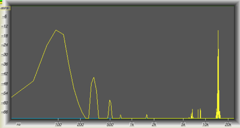
Up until now, it has been an accepted notion that clipper induced IMD was a by-product of deep bass and enhanced midrange/presence/treble content. When studying an example of the song Because of You, by Kelly Clarkson, it became evident the problem was related to clipper-induced IMD, except the example does not possess any bass spectrum of any significance.
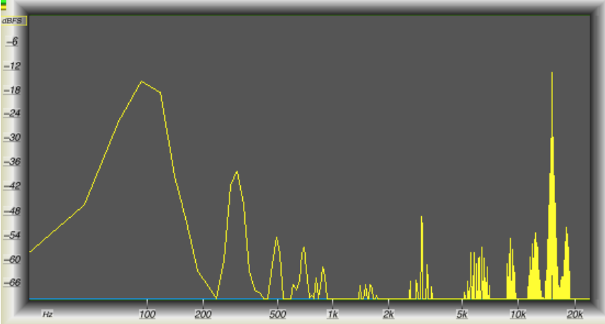
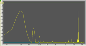
Notice in Figure 3, a segment taken from the Kelly Clarkson track, the dominance of signal centered at 500 Hz, and the range between 10 kHz to 15 kHz. Perhaps you might wonder what happens if some IMD tests were run on present clipping systems.
Under the Microscope
Performing an IMD test on a clipping system is quite easy. Two audio frequencies are mixed together, then passed through the system under test, and the output is observed on a scope and spectrum analyzer. In this instance, the clipping systems all employed the required 15 kHz low pass filtering and zeroovershoot control mechanisms found in broadcast processors.
For the test, 100 Hz was inserted at a level, which generated 3 dB of clipping. A high frequency component was mixed in at the same level, and 75 µs preemphasis was applied. The tests were run over the range of 5 kHz up through 15 kHz, while 100 Hz was used as a constant low frequency source.
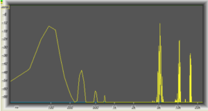
Figures 4 through 8 are the results of the tests.
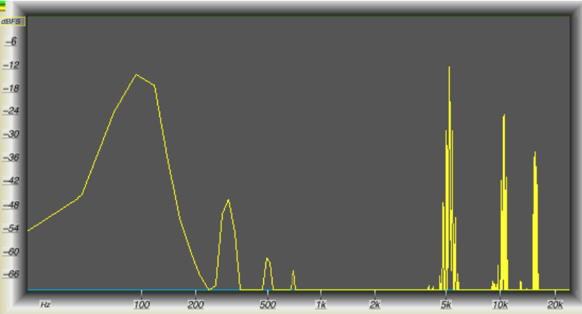
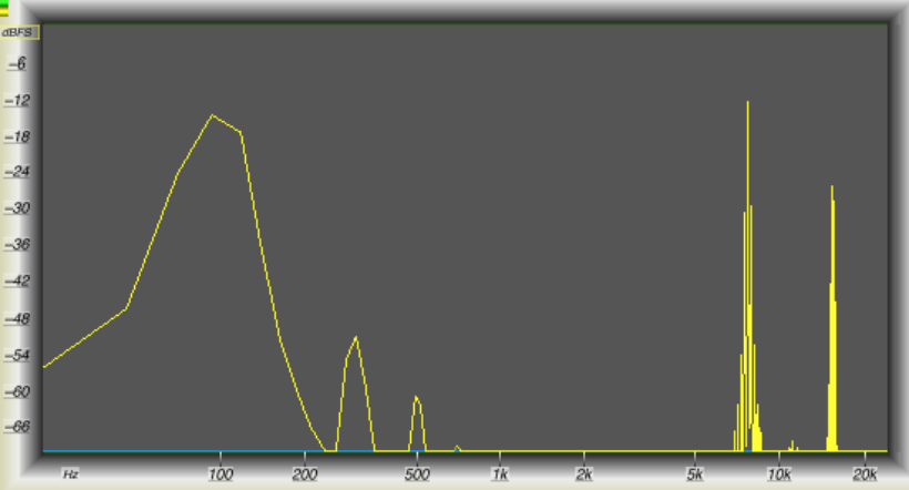
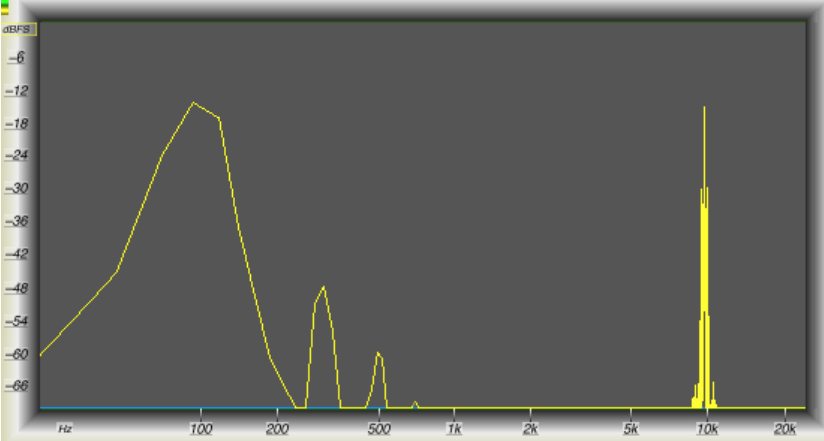
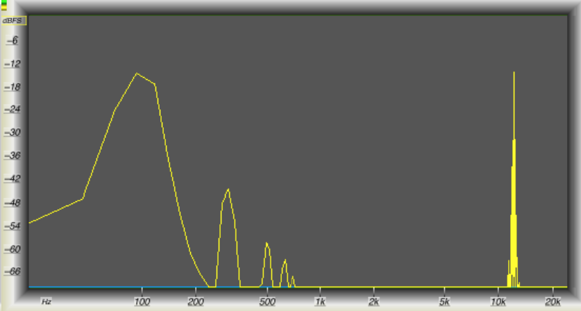
Notice as the upper frequency is increased, there is significant difference spectra that falls between the two fundamentals. This is extremely severe at 10 kHz, 12 kHz, and 15 kHz. If you recall the music example, this is very close to the spectral illustration in the Kelly Clarkson track. “Houston, we’ve got a problem,” and it is clipper induced IMD!
Clipper Systems, Distortion Cancelling, and Too Many Bands!
As said before, present day clipping systems all employ methods to control distortion. Of interest is that each of these use a static method to mask harmonic distortion when clipping is active.
The Kelly Clarkson example clearly illustrates harmonic distortion is not the concern, as it once was. Intermodulation, due to added presence and high frequency spectra, has overtaken the problem that once was dominated by harmonic distortion. Suffice it to say, all clipping methods must employ some form of harmonic distortion control, or they will not operate sufficiently enough to generate competitive-sounding on-air audio. Modern content now requires additional processing means to reduce induced IMD.
Suppressing IMD is significantly more difficult, as the constant difference frequency components are a non-stop moving target, whereas suppressing harmonic distortion can easily be predicted and controlled through a static filtering system.
Proof of this is demonstrated with an evaluation of present day distortion-cancelling systems. All of them employ static filtering to mask distortion components. They vary in range from broadband to five or six bands – or more.
All of these fail under aggressive processing. The broadband method suppresses harmonics, and some IMD at specific frequencies. The multiband methods are designed to insert gentle low-pass filters after multiband clippers in each audio band. This works, over a narrow range, but falls apart with aggressive levels of clipping. Multiband clipper/filtering is done in parallel architecture, and each singular band clipper is not able to understand what the others are doing. Therefore, the resulting filtered harmonics of each band interact in unpredictable ways, some of which exaggerate IMD.
And the Answer Is…
… not in the number of bands. Adding more bands or steeper filters does not improve or fix the problem! Anyone who thinks adding more bands of limiting, clipping and filtering to the system is wasting DSP cycles, computer MIPS, and generating a lot of marketing rhetoric.
The answer lies in understanding the range of frequencies that generate both harmonic and intermodulation distortion, then applying various masking means to suppress both simultaneously as they are created, something much easier said than done. It turns out to require a combination of breaking down the audio spectrum by octaves and interaction with the Gibbs Phenomenon. Adding SENSUS technology enables a clipping system that suppresses both harmonic and IMD distortion components, when aggressive processing levels are required.
More importantly this new clipping method does not employ the use of dynamic compressors or limiters to control depth of clipping, in order to minimize clipper induced IMD. There have been – and still are – a few proponents who do utilize this method to reduce generated IMD, but it is at the expense of added dynamic intermod which manifests itself as audio pumping and hole punching.
Proof
Now we will run the same IMD tests as mentioned earlier and offer the following results. Please compare Figures 9 through 13 to those of Figures 4 through 8 to see the results of both the old and new methods.

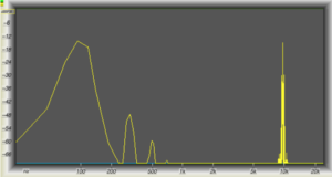
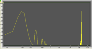
Comparing the two sets of tests, it is easy to see that for the exact same amount of clipping employed, midrange, presence, and treble IMD has been eliminated.
With the new method, Kelly Clarkson’s test segment does not possess any of the bacon frying sizzle annoyance as heard prior with all other clipping systems. As a matter of subjective observance, all audio auditioned through this new method, sounds cleaner for the same given level of loudness. It does not matter if the content source contains deep-rich bass or not, the audio signal is subjectively cleaner for the same level of loudness!
What Gives?
It is worth restating. The answer lies not in the number of limiters, clippers, and filters, but how all distortion products are dealt with interactively on an instantaneous basis.
Multiband clipping does not take into consideration any interactivity of outlaying spectra. That is where that method eventually fails. The proof is in the audio performance, with critical content.
While the above detailed description uses the clipping system for an example, the same technique, when applied to dynamic limiters also yields improved aural performance. For the same given amount of dynamic limiting, there is less perceived IMD. The benefits are two-fold: improved quality for the same given loudness, and added processing headroom that is now available when competitive situations arise.
Additionally, the RMS-based AGC/compression system maintains consistent levels for the limiters and clippers. The result is consistent levels through the entire processing system yielding quality and effortless loud audio.
Where Do We Go From Here?
That is the never-ending, age-old question, if there ever was one.
Our imagination is the only limiting factor. At Omnia, we never stop reaching higher. Already, we are in development to further the ideas discussed here. We currently have initiated the work to determine the viability of using single-sideband suppressed-carrier (SSBSC) as an improved transmission means for the present FM Stereo system. The interest is so strong that NRSC has re-opened a group to study it as an industry.
Fifteen years ago, we were the first to figure out the answer for non-aliasing clipping in DSP, along with an improved, cleaner final clipper. As broadcast and transmission methods have further evolved over the same period, so has processing. Fortunately, we now have – finally – acquired the power to delve deeper into a number of critical sonic issues like smart RMS, and induced IMD. Now we have solutions for those challenges.
– – –
Frank Foti and Cornelius Gould are the brains behind the Omnia.11 processor – and other audio processing solutions for broadcasters. You can contact them via email at: padrino@telos-systems.com and cgould@omniaaudio.com respectively.
– – –
Are articles like this helpful to you? If so, you are invited to sign up for the one-time-a-week.BDR Newsletter.
It takes only 30 seconds by clicking here.
– – –