

Old Guys, Experience, and Harris Flame Throwers

[January 2024] Robert Frost said: “Education is hanging around until you’ve caught on.” As Ron Schacht points out, this often is how broadcast engineers learn things. What you do with that education determines your value as a competent engineer – or someone who waits for the same events to come up repeatedly.
Experience is a great teacher, better than any book theory, and after so many years, an experienced broadcast engineer does not need manuals or factory help in many instances.
Experience also gives you hindsight on equipment that had features that were “good ideas at the time” but have proven to be serious mistakes. This meandering is mainly about some of the HT series of Harris FM transmitters we will get to, but in a roundabout way.
THE TEST OF TIME
When I was a young Whippersnapper in radio engineering, one of the then “old guys,” I think it was either Henrich Hertz or Guglielmo Marconi, said to me that if I had replaced the coupling capacitors in an ITC triple deck cart playback tone decoder board, more than once at the same station, I was working there too long.
Well, I was at one station long enough to replace them three times.
But our topic is not cart machines. Instead, we want to talk about the Harris HT series of transmitters, precisely the 5 to 10 kW range.
HARRIS HT SERIES
These guys have been around for a long time, and many are still running.
If you have one, especially if it is located in a not-so-nice site, hot in the summer, cold in the winter, and dirty all the time, pay particular attention. The Harris HT 5, 7.5, and 10 all have a serious flaw that could cost you – possibly an entire new transmitter building.
The crux of the matter is that these three transmitters came complete with a harmonic filter.
DESIGN CHOICE
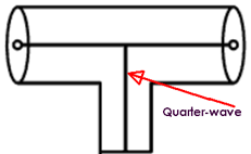
The harmonic filter, unlike many harmonic filters, has a shorted quarter-wave stub set to your frequency – it is the long stub about three feet long.
True, other transmitters use them. However, usually, the end that is shorted is silver-soldered and shorted to a good short. In contrast, the people at Harris made theirs adjustable, so one size fits all: you just move the short to the quarter-wave point, and you are set to go.
Of course, when you buy the transmitter for a specific frequency, Harris set the harmonic filter up for you. You only needed to mess with it if you changed frequency.
THE STUB IN OPERATION
Now, a quick review a shorted stub.
A piece of transmission line that is cut to one quarter wavelength has interesting properties. If you calculate the quarter-wave length, figuring in the velocity factor of the line and leave the end open, the other end will be a dead short at that frequency.
On the other hand, if you intentionally short one end, the other end will be an open circuit at that frequency, and a short at all others as you move from that resonant frequency. There is where its use comes in.
Let us say your station is on 93.7, the shorted stub, cut to 93.7 is an open circuit at 93.7 and therefore is a short at all other frequencies, so any harmonics are looking into a dead short and never get to the antenna. This is a great idea, and one that works very well.
Just one thing.
THE STICKING POINT
The issue with the Harris design, however, came from the ability to move the shorting point.
This feature relies on tightened connections between the inner conductor and the outer conductor. Over time, with dirt, dust, temperature changes from cold to hot, this connection becomes loose or corroded and it is not a good short any more. The “short” is beginning to have resistance and, though it might be slight, it is going toward an open (which you will remember is a short at the resonant frequency).
To illustrate the problem, let us say that, over time, this connection has developed one-half Ohm of resistance. Ok, now the transmitter is producing 5 kW. It is more or less a constant power device, unless some VSWR device shuts it down, so it will continue to produce 5 kW.
[the_ad id=”10548″]
CURRENT IN THE WRONG PLACE
Recall P = I2R? Ok, P = 5000 and R = .5 Ohm so I2 = 10,000 or I = 100 amps.
I have laid some really nice welds down with a lot less current than that! So, the allegedly shorted end gets hot and as it gets hot, the connection gets worse, the resistance goes up, it gets hotter until as I have seen three times, it melts and the entire red hot molten end falls off on the floor.
Usually then the VSWR will kill the transmitter but, if the floor is wooden or there is a pile of flammable stuff when it falls, I hope your facility is insured, you will need it.
CATCHING ON
As I mentioned, I have seen three of them do this – and I caught a fourth one in time.
I happened to be working up by the stub, replacing a coil on a co-located AM phasor when my arm came in contact with the end of the stub and I lost about four layers of skin.
I helped the station engineer take the stub apart and clean it shiny and reassemble it nice and tight replacing any hardware that was overheated. We got done and it ran cool, not cold but cool.
Since then, I have suggested to anyone with one of those rigs to check those stubs, start with a glove and work down to a bare hand to make sure it is not hot. They should be checked regularly, especially, as I said earlier, if the site is less than clean and not temperature controlled.
Remember, the site you save, may be your own.
– – –
Ron Schacht (K3FUT) is a contract engineer in South Dakota. Over the last 60 years he has built some 100 stations, including a dozen with directional antennas. You can connect with Ron at ron.kq1380@nvc.net
– – –
Would you like to know when more articles like this are published? It will take only 30 seconds to
click here and add your name to our secure one-time-a-week Newsletter list.
Your address is never given out to anyone.
Return to The BDR Menu