

Inspecting an AM Tower
[December 2012] Regular inspection plans and maintenance can go a long way to preventing silence on the dial. What should be on the inspection list, and what should be outsourced to a professional tower crew to inspect?
For most AM stations, the tower site is often their one major single point of failure. Few have a “spare” tower, so the loss of a tower can be crippling.
Furthermore, it is much harder to have an “Auxiliary Site” for AM than for an FM station. And, with zoning issues being what they are, in many places just replacing an old tower is almost impossible.
These reasons and the desire to control ongoing maintenance costs is why it is so important to know the condition of your tower and keep it in as good condition as possible.
Tower Foundations
All towers, whether in AM, FM, TV, two-way, or multiple use have a few things in common. For example, they are all built on the ground. Most use guy wires. And, they are expected to stand straight up in the air.
That last statement may sound obvious, even silly. But some older towers – and some on poor ground – can be seen to be crooked with the naked eye. Often though, it happens slowly over time. That is why a good professional tower inspection usually starts with the tower foundations, the guy wires and anchors, and their tension.
Another reason a tower inspection starts at the ground level is that all that steel delivers a tremendous amount of downward pressure. Watt Hairston once calculated WSM’s 808-foot AM tower and guy wires exert over 300 tons of downward pressure. And what can we say about those 2000-foot monsters in the Upper Midwest?
Clearly, the ground conditions are a major part of whether a tower will stand for decades or fall in an ice storm. That is why consultants and tower crews hire engineers to do a soil analysis, and determine for the installation how deep and wide the pier should go, what sort of concrete and rebar is to be used, etc., both for the tower base and guy anchors.
In one unfortunate case, a four-tower array built in a field started to sag and go way out of plumb when the field got wet. In the end, an expensive project requiring dual 50-foot-deep piers and steel bridge supports was installed to keep the towers from falling now or in the future.
Ground Level and Below
The first check that station personnel can do, as will a tower crew doing an inspection, is to look at the tower base.
What you do not want to see are cracks or other damage (as from lightning) that might make the foundation collapse, bringing the tower down. Sometimes it is obvious, sometimes you need to watch over time, to see how anything from lightning strikes to subsidence to earthquakes may have compromised it.
But just looking what you can see above ground may not be enough. If your guy anchors were installed in the plain dirt, the anchor rods may be slowly dissolving into the ground. And, eventually, under the right conditions, they will snap.
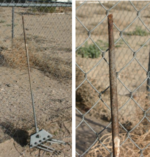
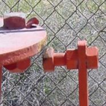
This is an ex-guy anchor rod
Unless you see the cement for an anchor base, the way to find out the condition of your guy anchor rods is to – very carefully – dig down a few inches around them and look to see if they are encased in concrete or if there are surrounded by dirt down to the anchor.
As you go, check for corrosion. If you find it, immediately stop and call the tower company. Let them redo the anchor, fully encasing it properly in inert cement. Even better: use coated anchor rods embedded in the cement.
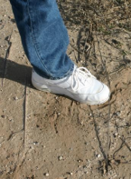
One more important check below ground is the condition of your ground system. Those radials around an AM station tower are, in effect, one-half of the antenna. Any stolen, missing, or damaged ground radials can reduce transmission efficiency and station coverage. Exposed radials should be reburied as soon as discovered, lest they are further damaged – or worse, prove to be an open “invitation” to local copper thieves.
At Ground Level
If everything checks out with the foundations for your tower(s), it is time to work your way up through the tower, thinking of it not as just a pile of steel, but as a system.
Guy towers normally will have three sets of guy wires, at a 120-degree spacing.
Depending upon the size of the tower, the length of the wires, and windload, a specified tension is set for each one. That is why you normally will see a turnbuckle at the bottom of each wire – so the tension can be adjusted. A guy anchor encased in cement with turnbuckles and insulators
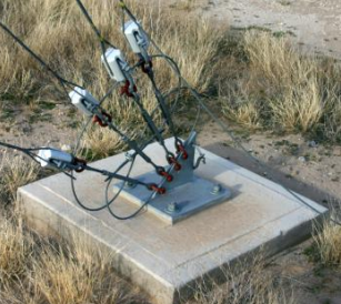
A guy anchor encased in cement with turnbuckles and insulators
Tensioning is not a casual process, as much as it might seem so. Over time, it is normal for the guy wires to stretch a bit; temperature changes help the process.
If there is a significant difference in the guys, a tower could crook, twist, or even fall.
Just to give you an idea of the forces in play, a typical guy wire on a 200-foot tower will measure 1000-1500 pounds of tension, again depend- 3 ing upon the various factors (tower size, guy size, wind load, etc).
Few stations have a dynamometer sufficient to measure the guy wires, so this is one task where a tower crew is a good investment. Sometimes, people will grab each guy wire and see how far it will pull, as a way to gauge the tension. But this is only a most coarse indicator.
By the way, make sure the guy wires have good clearance from obstructions. Having your guy wire go through a tree branch is just asking for trouble. If there are any branches near the wires, cut them down and haul them away.
Insulators
In the picture above, you may have noticed guy wire insulators just above the turnbuckles. Their condition is your next concern.
Because the guy wires are a large fraction of an AM station’s wavelength, they need to be broken up into shorter sections. Each wire will have a number of ceramic insulators, spaced according to the specifications of the station’s consulting engineer, to minimize re-radiation.
The inspection of the insulators will check three major points: (1) that each insulator is intact, not broken, (2) that there is no excessive dirt or other matter that could cause arcing across the insulator and negate its effect, and (3) the absence of rust on the wires or the preform inside the insulator.
The Big One
Not all towers have base insulators. FM and shunt fed AM towers do not need them; the bottom of such towers is at ground potential.
Most series fed AM towers though do sit upon ceramic insulators to keep the tower from contacting ground potential. Such insulators range greatly in size – usually based on the voltage expected at the tower base – from very modest to huge.
The bottom of the base insulator normally has a slightly rounded “plate” so the tower can “rock” back and forth slightly under windy conditions. Sometimes you will see the base insulator in two parts. Watt Hairston and the WSM base insulator. The Lapp insulator is designed to handle twice the calculated downward pressure on it.
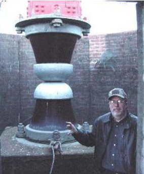
Watt Hairston and the WSM base insulator.
The Lapp insulator is designed to handle
twice the calculated downward pressure on it.
Two things can go wrong with your insulator, and needs to be checked regularly. The first is a crack in the ceramic. Such a crack will lead to tower failure – think water, think ice, think bigger crack – and should be attended to right away.
The other potential problem is related to excessive dirt could cause arcing or even an impedance change.
Locating and removing such dust, dirt, and other wind-born materials should be on the regular maintenance schedule. It should not take a formal tower inspection to discover carbon tracks forming on the insulator.
In fact, in the “Good Old Days,” it was a regular task for transmitter engineers to clean the base insulator – and still should be on the transmitter engineer’s regular list of important checks.
There are just a couple more aspects of the tower inspection at ground level that we should discuss this time.
The ATU and Feedline
The ATU (Antenna Tuning Unit) and feedline to the tower should also be checked for their integrity.
Each AM tower has an ATU next to it. This is to match the transmission line to the tower’s base impedance.
A good inspection checks to see that all of the components are in good condition, the hardware is tight, there are no bugs jamming the lightning gap, and there are no animals or insects making the ATU their home.
The feedline needs to be securely connected to the tower. A loose feedline will arc, create intermittent connections and generally wreak havoc with the transmitter, causing you to go off the air.
The check is simple, look to see that the weld is solid. If you can visit when the station is off the air, you can check the mechanical connection by hand.
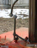
Ball Gaps
There are usually two important gaps at each tower, the ball gap at the tower base, and the lightning gap in the ATU.
The ball gap is there to grab as much of any lightning stroke as possible and push it right on down to the ground. The gap in the ATU is sort of a backup, and should not be the one you rely upon to protect the transmitter.
As you look at the ball gap, the balls should be side by side, not one over the top of the other. Otherwise rainwater and other contaminants could create a sort of bridge, resulting in an arc over the gap, and either transmitter cutback or total failure. Not so good Better – water, etc will not easily bridge this gap
One “Rule of Thumb” says that for each kW of power, the thickness of a credit card will be the right width of the ball gaps. But that does not account for the different potentials you may find at a tower base.
To correctly set the ball gap spacing, adjust it during hot humid weather at a voltage just above the maximum voltage that will be developed by normal transmitter operation. For example, run 105% transmitter power with positive modulation exceeding the FCC 125% modulation limit to accommodate any brief overshoots that are not prevented by normal audio processing techniques. Set the gap accordingly so that no arcing occurs.
The goal is find the lowest arcing voltage that will never happen during normal operations.
Document
As is often recommended, document the things you see during an inspection – or have the tower crew do it for you.
Take pictures of the key parts of the system as you or your tower crew inspect. This way, you have a “base” to compare, if something looks different at some point.
In our next installment we let the tower crew climb the tower, and discuss what they will look for as they inspect the metal, the paint, and the lighting systems.
– – –
The BDR