
FM Antenna Systems Maintenance Part 1: Preventing Signs of Impending End of Life

[September 2018] How can you tell if your tower or antenna needs maintenance? A good start would be a presentation from an antenna manufacturer on how to tell if your antenna needs repair or replacing – and how to do it.
Much of the following information came from a presentation by Tom Silliman at the PREC 2018 conference.
The only time most engineers see their antenna is when it is on the ground before installation.
After that, the antenna lives hundreds or well over thousands of feet above the ground, where it is difficult see any changes until something bad happens. Our goal is to identify and delve into the factors that cause end of life for transmission lines, towers, and antennas before they can cause failure.
To do this, we will talk about your system from where it leaves your transmitter, the building, goes up the tower, the tower, and the things the tower can do to your antennas to shorten their lives.
Dangers That Can Kill Antennas
Some of these things are obvious to everyone:
- Time in use (during a 24-hour stretch)
- Time in use (age of antenna)
- Vandalism
- Wind caused movement; especially when brackets are broken.
- Tower or pole vibration – guy wire galloping/snubbers
- Vortex shedding (mostly on pole mounted antennas)
- Lightning
- General storm damage, including loss of air.
- Salt at sea coast location.
- Other damage to coax.
As we will see, you can plan for dealing with some of these issues. Others cannot be predicted, but there can be a plan of action in place.
Preventing Antenna Failure
Of course, proactive stations do schedule regular inspections of their tower(s) and antenna(s).
Setting up a maintenance plan is not that difficult – but waiting until problems show up is the best way to ensure spending a lot of money, as well as dealing with lost air time. Being proactive will result in your seeing tower and antenna deterioration before it reaches any danger point.
Working on it this way, you will ensure the best radiation possible for as long as possible.
Daily Time of Use
In the old days, a lot of stations would operate until maybe 1:00 in the morning, then go off the air until six. The problem is the antenna would cool off.
The transmission line and antennas and feed lines are limited to 20 feet. The reason is, if you go to 30 feet, the difference between the outer and the inner temperatures will cause the bullets to pull out of the inner conductors.
These bullets do move as the local temperature changes, but if the station goes off the air every night, you will get additional deterioration as the feed line heats up in the morning and cools off at night.
Time in Use
Metal does fail eventually.
Such failure shows the difference between the inner and the outer expansion and what can happen – something. I have seen many times where I replaced bullets that had failed.
That can accelerate the end of life.
One example was in Oklahoma on a mountain. The tower was only 200 feet, but the station kept having intermittent noise problems with the on-air signal.
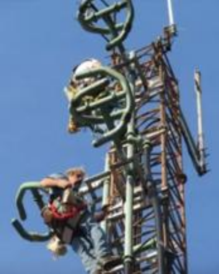
I had the station engineer get a boom box and place it at the bottom of the tower. We put the antenna on at full power, and I began climbing up the tower to the antenna (Note: This was before the radiation exposure standards had been written).
As I went up the tower, I started tapping on the antenna harness, and finally found that when I tapped on the center feed, I could hear the noise coming from the radio at the base of the tower.
When we turned it off and opened the input connection to the antenna, I found that the input bullet was all yellow and ready to totally fail.
This is what the bullet looked like. We replaced the bullet, cleaned up the outer conductor, placed the inner conductor back, put it all back together – and the noise problem stopped.
The problem would have been found earlier with routine maintenance of that antenna but, in fairness, I did find it before it created a system failure.
Internal Arcs
What is interesting about arcs inside coax is that the arc always travels up (hot air rises), and then the debris falls down.
If you do not turn the transmitter off right away, the first thing that happens is arcs begin at the Teflon insulators because the insulators in the coax have particles or water or whatever falling onto them.
Then, over time, the arcing works up between the inner conductor and the outer conductor of 3 the coax. When you look at the inner conductor, you can see the lines going up the inner conductor from the traveling arc. It eventually melts the copper inner conductor and that condition results in more arcing that burns everything up, with the soot from the arcing again falling onto the next insulator below the arc.
This next insulator begins arcing and does the same thing. So long as the transmitter does not turn off, the arcing just keeps going on, working its way down the coaxial feed line to the transmitter itself.
If arcing does occur, antennas can be repaired or rebuilt to extend its life using new bullets, new insulators, or new inner conductors. But if excessive arcing occurs due to the transmitter remaining on, the entire system might need to be replaced.
Time Between Failures
There are a lot of things you can do to extend antenna life.
If your antenna is 10 years old and you are seeing some changes in return loss, it might be time to take it down and do some maintenance. Rigid coax can also be rebuilt to extend its life. I have done this many times. Often, the inner conductors and outer conductors can be reused, with only new bullets and insulators being needed.
One interesting project in which I was involved was with an antenna that had been up in service for 25 years.
The antenna had an internal pressurized feed enclosed in a fiberglass insulator. The insulators in the antenna elements had deteriorated from exposure to the sun.
You even can see where the resin in the fiberglass insulators had been eaten out – and you could actually see loose layers of fiberglass blowing in the wind.
In this case, rather than painting the insulators, we recommended a rebuild. We brought the antenna down one arm at a time and took them all apart. We replaced all the insulators, put it back up, and now it is ready for another 25 years of service.
Other Kinds of Antenna Failures
 Here is a shot of a transmission line that actually runs through the aperture of the bays of an active sidemount FM antenna. You can see it is missing one of the little insulating buttons that keeps the rigid line outer conductor from touching that metal hanger.
The induced current that flows on all metal components near an active FM antenna can cause a potential difference to occur between that bracket and that copper outer conductor.
This then can cause a arcing to occur between the bracket and the coaxial outer, and can result in a burn causing an external hole in the coax. It shows up because the antenna starts losing air pressure.
At the shop, we have a drawer full of these buttons. When we return to antennas like this one, we have some of those buttons in our pouches – we replace them if necessary.
By the way, I would suggest using Teflon buttons. I have seen manufacturers that use nylon buttons – buttons which will melt in high RF fields. We will only replace them with Teflon buttons.
This is just a simple example of something that could have become a terrible problem if we had not caught it.
To prevent it, you do an inspection at least every two years.
 This side-mounted antenna is an example where we reported the insulators had started to deteriorate due to solar exposure after 25 years. You could see where they were leaking and where they were layered.
Vandalism
The clearest symptoms of vandalism are unexpected VSWR changes or a significant loss of pressure in the antenna.
Usually it is the result of someone attempting to shoot out the tower lights with a gun, but instead of hitting the light, the bullet hits the antenna or the antenna feed line. The hole is usually right where the lights are on the tower.
Over the years, I have seen this maybe 30 times. The damage can be fixed but it does require maintenance.
If the bullet ends up inside the coax, that can be is a problem: arcing can result.
On the other hand, if the bullet just glances the coax or goes through it leaving a bullet hole, you can go up there and repair the hole.
If the feed line is flex line, you cut the cut the jacket off and put a piece of copper strap around it, soft-solder the strap to the copper outer conductor, and you are back in business.
Why Towers Fail – They Move Too Much
The prime cause of tower failure is guy wires not tensioned properly.
Tower design should take into consideration the following conditions.
- Ice on wires
- The need for snubbers
- Improper reinforcement design
- Antenna installed without an analysis of tower prior to the additional loading
If antenna failures occur in less than three years after installation, the tower should be analyzed to determine if excessive movement is causing the premature antenna failure.
Benefits of Analysis
Towers can be analyzed today much more accurately with finite element programs versus that of a beam column.
Some of the analysis that we did showed terrific problems on one tower, the tower on top of the Empire State Building. We were hired by the MTV of New York City, the TV broadcasters that were using the Empire State Building as a broadcast site, to map that tower and run an analysis of the tower.
The Empire State Building antenna tower was built quite a few years ago and has really sharp tapers.
If you look at towers today, you might have a taper that takes 20 feet to go from say 5-feet to 3- or 4-feet wide, but the Empire State Building’s tower has tapers of 5 feet to go from 8-feet to 6-feet wide.
It turns out that with sharp tapers that leg moments can be excessive. Analysis of that tower with a beam column analysis showed that the tower was OK, but using a program that used finite element analysis showed that the tower was overloaded by 45%.
Today, towers are commonly analyzed using finite element calculations, a great improvement in analysis technique.
Understanding Movement
At ERI, we decided to come up with a standard for a tower movement, so we defined the radius of curvature of the antenna aperture to be 3000 feet at a service wind speed of 60 MPH.
We wanted the radius to be uniform so that no part of the tower would cause a high stress point in the side-mounted antenna harness.
From trigonometry, the angle in radians, ϴ, times the radius of an arc is equal to the length of the arc. The distance of X is the horizontal distance to where the tip of the mast moves horizontally in the wind.
Using trigonometry, one can calculate the deflection of the tower section if the deflection is uniform. In this case, the top of the tower moved 7.2 inches when the tower bends uniformly with a uniform bending radius of 3000 feet.
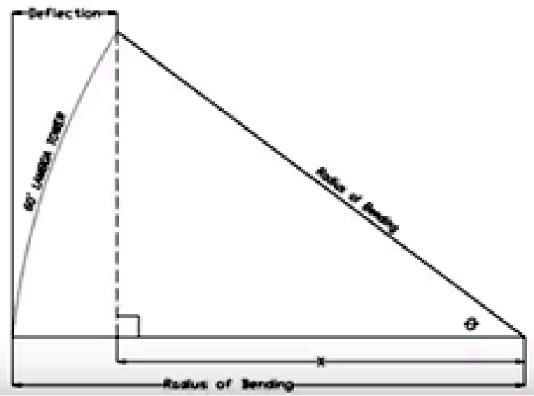
You can see in the example that the tower forms an arc and the radius of bending is the same at the top as it is at the bottom. I published a paper on this years ago because everybody kept asking how you calculate uniform tower deflection.
Again, in the example above, I have assumed a 60-foot tall tower and specified a 3,000-foot radius of uniform curvature to keep from hurting the antenna.
The deflection calculation is shown below:
- Assume a 60 foot tall Lambda Tower
- Specification of radius of curvature for the Lambda Tower is R = 3000 feet at full wind design under G
- R(Ɵ) = 60 feet where ϴ is radians
- Ө = 0.02 radians = 1.1459 degrees
- X = (3000) cos1.1459 = 2999.4 feet
- Deflection = 3000 – 2999.4 = .6 feet
- .6 feet = 7.2 inches
From trigonometry, the angle ϴ is in radians. The distance of X was a tower deflection of 7.2 inches.
We developed this tower stiffness standard at ERI in 1990, and first used it to replace a thin pole in Pittsburgh, PA. That antenna had been failing on a yearly basis.
Since we replaced that pole with our first Lambda Tower, the antenna has not failed. Another advantage of the ERI Lambda Tower is that the tower is custom designed so that the vertical spacing of the horizontal tower members is set at a half wave of the user’s frequency. Thus, the scattering from the tower is identical for each element in your side-mounted array.
In Part 2, we will pick up with how galloping guy wires can hasten the end of a tower and antenna’s life.
– – –
Tom Silliman is President of ERI Inc, in Chandler, IN. Tom is well-known for his work, whether designing and constructing towers or working on them and antennas at hundreds and hundred of feet. You can contact Tom at tom@eriinc.com