

Feeding Clean Air to Your Transmitter

[August 2022] A clogged air filter is a problem. Even if it is still keeping most of the dust and dirt out, it is likely that the gear it is supposed to protect is air-starved, and hotter than it should be. But, can your replacement cause problems too? Jeff Welton explains:
From time to time, a discussion breaks out on the BROADCAST [BC] forum (www.radiolists.net) centering on air filters and airflow – site cooling in general.
As this is something I have had to study from the “manufacturer’s recommendations” perspective, I thought I would weigh in with some thoughts and suggestions to help folks cope with questions they might have.
AN ESSENTIAL PART
Filters are there for a reason.
Never remove air filters, unless to replace or clean them.
Removing them because they are plugged up with dirt and not replacing them simply means that all of the dust and dirt that they had been catching – and which caused them to be plugged – will now be free to proceed to the next stage in the cooling system. At some point, that dirt will find its way to a high voltage connection and be a prime candidate for arcing.
There are several important points to consider when replacing air filters, the very reasons why the manufacturer chose the original filter.
THERE WAS A REASON
Does your equipment come with a metal mesh filter that is hard to get and you do not have water on the site to clean it?
Replacing it with a pleated paper filter sounds like a good idea, right? Not so fast. That particular mesh filter was chosen for a reason – probably because it allows a high volume of air to pass through (at least when it is clean!).
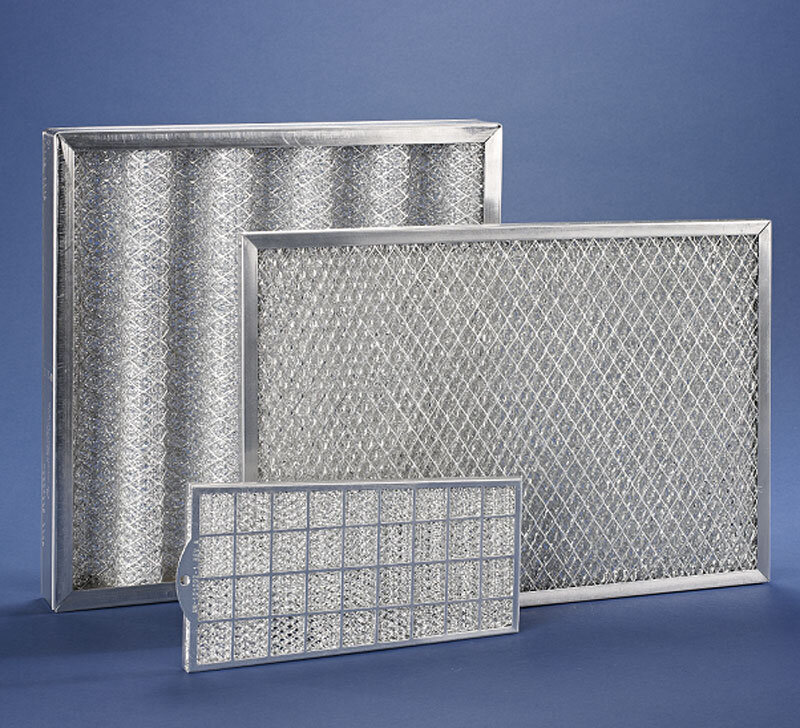 By the way, one thing to note about metal mesh filters is that they do not work optimally unless they are sprayed with a sticky solution which is used to trap dust.
This spray should be applied whenever new, untreated filters are installed and whenever they are washed. It is sold under the name “Filter Coat” and is available from a number of sources (and prices) as Filter Coat 412 or Filter Coat spray.
By the way: although this is not usually the case, it is possible a metal mesh filter was used for shielding purposes – in relation to LTE interference, for example – so, in those cases, reducing the shielding really is not something we want to do! –.
THE RIGHT REPLACEMENT
In replacing filters you need to consider some specifications: the MERV (efficiency) rating and the PPI (pores per inch), the specific material, and the right size to fit the cabinet opening.
To explain the terminology, MERV stands for Minimum Efficiency Reporting Value. Effectively, all it represents is the size of the particles that can pass through the filter (pore size, in other words). The higher the MERV (generally on a scale of 1 to 16), the smaller the particle it will pass – however, the greater the pressure drop (back pressure) across the filter, as well.
This is where PPI also comes into play – because a 30 ppi filter with MERV 8 rating will not pass as much air as a 40 ppi filter with MERV 8. It is not enough to simply know the MERV rating, you need the full specifications on the filter you are looking to use.
For what it is worth, a MERV of 5 to 8 should be more than sufficient for the typical transmitter site.
MORE IS MORE
Another factor not mentioned yet is the surface area. A pleated paper filter has a larger surface area than a flat filter would have.
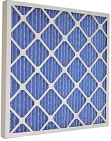
Therefore, it stands to reason that a pleated filter could pass more air than a flat filter having the same MERV and ppi specifications.
Furthermore, a 4-inch thick pleated paper filter would be able to pass more air than a 2-inch thick filter (although at this point, we would also have to consider the limits of the actual airflow opening, so the improvement is not linear).
Here is another important point to not, when you are looking at replacements: Sometimes odd filter sizes are chosen to prevent a wrong choice of replacement.
As you can see, for all of these reasons, simply replacing the filter in your transmitter with an easier to get item that has the same physical size is not a real good idea.
WHEN MORE AIR IS NOT BETTER
By the same token, replacing the filter with one that allows a higher volume of airflow, but possibly at the risk of passing larger particles of dust, still is not the best solution, either.
Keep in mind that not all transmitters are positively pressurized. Nautel, for example, tends to promote site improvement, and our transmitters are not designed to be specifically pressurized to keep dust out when improving the site is the preferable solution.
With this in mind, we produced a web seminar on transmitter cooling and some of the things that could be done to improve the situation without breaking the bank. (The discussion is available here; the air handling part starts at 31:10, if you do not want to sit through a half an hour of me gabbing about lightning protection!)
[the_ad id=’7866′]
THE CLEAN AIR ROOM
One thing about air handling in general – if you add a “clean-air room” to your site and double filter it, then positively pressurize the entire transmitter room, dust will have a hard time entering into room.
At that point, the transmitter fan filters do become somewhat more optional.
To do this could be as simple as adding a 4-foot by 8-foot room at the back of the building, putting all of your intake fans on the outside wall of that room, then opening the wall between this room and the transmitter room, walling it up with bag filters, or something with a higher MERV rating.
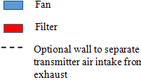
For example, you could use MERV 4 in the filters on the intake fans, then MERV 8 on the “Wall’o’Filters”.
CORRECT AIR FLOW FOR CLEAN
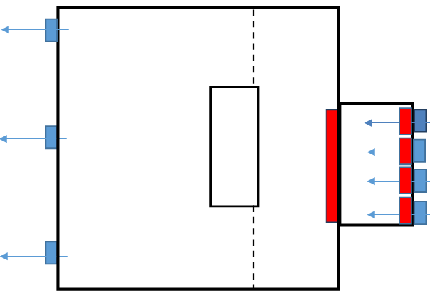
Now here is the trick to a having a real clean room: bring air into the room at a volume greater than the ktotal throughput of all equipment in the room.
So if you have a single transmitter that pushes 2000 CFM, bring 4000 CFM into the room.
Try to locate the equipment in such a way that it is between the air inlet and the exhaust fans, with its internal airflow oriented in the same direction as room air flow. Then install an exhaust fan that removes more air than the equipment throughput, but less than the intake – so, say 3000 CFM for the above example.
This results in excess air being forced out of every crack and crevice in the transmitter room, allowing no dust to enter, as all intake air is coming through the double sets of air filters.
Obviously, exhaust fan placement will be dictated to some extent by building layout. In addition, if it is not possible to physically separate equipment intake from exhaust, then exhaust fan locations may be adapted to accommodate.
Finally, remember these are suggestions only. Obviously every site and every budget will be different, so what works for some may not be viable for others. I am happy to discuss specifics with anybody, whether you are a Nautel customer (yet) or not!
– – –
Jeff Welton is the Nautel Sales Manager for the Central Region of the US. A veteran of many on-site trips to help customers, Jeff is always ready to help. Contact Jeff at jwelton@nautel.com
– – –
If you would like to know when more articles like this are posted,
please take 30 seconds and click here to sign up for our one-time-a-week BDR Newsletter.