
Checking it Out: ExpressPCB CAD Software

[September 2012] Have you ever had a need for a custom printed circuit board? Perhaps it is for a small project that you developed, but a few copies would be great.
Jim Pollock talks about a service he likes.
From time to time I like to design little projects to accomplish various tasks.
Often, I need – or want – several copies of the project for myself or to share with others in case multiple copies are to be built later. And just as importantly, I wanted to avoid the tedious moments associated with the point-to-point “dead bug” approach.
What I have found especially useful over the years is the free printed circuit board CAD software from Express PCB for years. ExpressPCB is a great tool for producing PC board prototypes quickly.
ExpressPCB
Sometimes, I have used ExpressPCB to bypass the resource constraints at a workplace where the CAD folks were severely backlogged.
If the circuit and layout are carefully designed and implemented, then ExpressPCB is a good way to circumvent that situation. (Some might call that “going rogue.”)
The software has a robust component library, which includes surface mount parts. Users can also build and share a custom component library (with precautions.)
The software consists of two platforms: a Schematic Capture and the Printed Circuit Board Layout.
The Rules of “Free”
There are a few points to keep in mind when using this free software:
- There is a size limit for the PC Board: 2.5 by 3.8 inches; 0.060” board stock.
- Only 2 or 4 layer boards are available. Single layer boards are not an option.
- The only place to order boards is from ExpressPCB
- The software does not generate Gerber or Eagle compatible output files. (I do not find this especially objectionable because you can save time by not having to shop around or generate, manage, and maintain CAD output files. Express PCB takes care of that stuff.)
- There is no autorouter. You do have to place the traces yourself manually.
- Manual overrides must be used with caution. It is possible to stitch and short power planes together with a thermal relief pad to a power plane. Make sure that you have selected only one layer for that particular pad.
- Copy-Paste is not an option in the PCB layout. You can save on costs by placing several circuits on a single board and cut them apart. However, each circuit must appear on the schematic, and be individually placed and routed on the PCB artwork.
- The schematic capture system allows copy-paste of circuits, but the sequence numbers must be changed manually to prevent part sequence error warnings.
If you can work within these “rules,” I think you will find ExpressPCB to be a very useful tool.
Putting it to Use
To demonstrate the service, the following circuit board was produced with the Express PCB software. It is the analog front end for an RF dBm meter: a digital panel-mounted DC Volt meter for the readout.
The design is centered around the AD8307AN Logarithmic and Demodulation Amplifier by Analog Devices, Inc. The dynamic range of the dBm meter is -70 to +15 dBm, from 100 kHz to 200 MHz.
(The project was inspired by an article written by Rick Littlefield in the August 2000 issue of QST. His design featured a ten-segment LED bar graph as the readout device.)
A Schematic Sample
Schematics can be transferred to a “word” document by creating a “Screen Shot” and pasting it to the document.
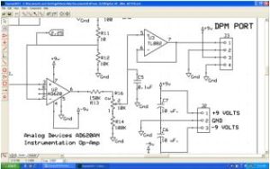
If preferred, the schematic page(s) may be exported to a PDF file, but each page must be printed to PDF as separate files.
PCB Artwork
As you use the program, the schematic is turned into the PSB layout.
Here is how the component side looks:
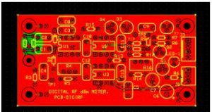
The component side with silk screening and the ground plane highlighted in red
You also can see the “X-ray” view of the PCB:
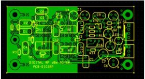
X-Ray View
The silkscreen layer is shown here as an overlay with the solder side layer. The view of the “solder-side” traces is that of looking through the board from the component side.
The Finished PC Board
After using the service, the finished PCB is delivered ready to populate with parts. A few minutes later, we are ready to test it out.
This particular PCB is fairly small. The quarter is shown to give scale.
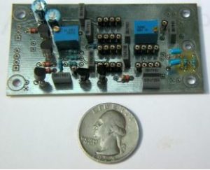
The circuit, all ready to go
The finished PC board with all components and IC sockets installed, is ready for wiring to the Digital Volt Meter, the RG-174 pigtail to the rear panel mounted BNC connector, and the power on-off switch.
The Finished Project
Of course, it was satisfying to note the project worked the first time that is was fired up.
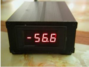
The circuit at work in the meter
While sitting on the kitchen table, the dBm meter reads -56.6 dBm with an 18-inch telescoping whip antenna. My house is within several miles of two 50 kW AM stations and a Class-A FM station. It is an RF rich environment. One of the stations (WPHT-AM) puts 100 mV into the kitchen.
By the way, without the whip antenna, the “background reading” is -75.4 dBm, which is the noise floor of the log-amp. The log-amp intercepts its characteristic logarithmic transfer curve at -70 dBm.
What Will it Cost?
Of course, any PCB will depend upon the number of holes, and the number of hole sizes specified as driven by the parts library.
For this particular project, the costs (including shipping to New Jersey) are based upon criteria in the following table as of August 14, 2012:
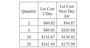
- Standard Service
- 1.6” x 3.075” boards
- Shipping to New Jersey
Note: shipping costs are specific according to the shipping destination plus applicable state sales taxes. (This information is contained in the customer profile prompt menu.)
Obtaining a Quote
Obtaining a quotation is done by opening a pull down menu, and filling in prompts for quantity, PC board options, and shipping preferences.
When ordering the boards, I decided to forego the silk screen printing on the component side. Silk Screen printing makes no sense unless you opt for the SMOBC (Solder Mask Over Bare Copper) process too. These two options are quite pricey.
I ordered two PC Boards. As noted in the table above the cost for both boards, with shipping, was about $80.
However, for those onesy-twosy orders, and engineering fire-drills, the silk screen can be omitted; just use your laptop PC as a way to view the silkscreen display as the parts placement diagram.
My experience with Express PCB was very positive, and I highly recommend them. They are very effective in providing resources that are otherwise not available. Their service is very prompt. PC boards can be delivered overnight depending upon your shipping preference.
Their web address is:
http://www.expresspcb.com
ExpressPCB Features
- A robust component library, which includes surface mount packages
- User defined custom component library.
- PCB artwork and schematic linking to facilitate error reporting.
- Schematic and PCB Error Analysis.
- Generates reports on floating pins, single ended nets, duplicate part sequence numbers, library errors, PCB trace and pad spacing violations.
- Multi-page schematics are supported.
- Comprehensive “Help” file & tutorials.
- Configurable trace widths, and power plane definition.
- Configurable power plane “void” areas.
- Node highlighter: find all pins (nodes) on a net by clicking on one pin in the net. All nodes on the net will light up in “blue.” All you need to do is connect the “blue dots.” For this to work, the PCB layout must be linked to the schematic diagram.
- Interactive online price quotations and order execution via PayPal.
- The flexibility of ordering boards with a component placement silkscreened on to the component side of the board.
- Plated thru holes are standard.
- Schematic Diagrams can be “printed” directly as a PDF file, or to other output utilities such as Microsoft document writer.
– – –
James W. Pollock, P.E., C.B.T., C.B.N.T, is a consulting engineer based in Mt. Laurel, NJ. He can be contacted at: jim@jimpollock.net