

A Modified Intake Air Filter for Continental/Collins FM Transmitters

[July 2010] If you maintain a Collins 831G2 or Continental 816 Series tra nsmitter that is not located in a “clean room” and is ventilated with outside air, and you are tired of having to repeatedly clean out the transmitters insides, or if you have had reliability issues due to foreign things that get inside the unit, this modification may just be what you need.
Back in the late 1970’s one of our trusty Collins 831G-2 transmitters ingested its factory provided foam intake filter. Since I was in charge of a large room at a site with multiple copies of this transmitter, and its descendant, the Continental 816R series, this event started me on a quest to provide a better filter, as well as one that would not end up inside the transmitter when it failed.
A Unique Design, With One Problem
![]()
Several 831G transmitters – and more lined up in back of them!
A great deal of credit is to due Collins (and later Continental) on their unique design that forces all the air entering the transmitter to be filtered before entering from the top of the box, pressurizing the cabinet.
However, where this design falls short is in the – amount – of dirt and debris that the filter will let inside. Especially in large rooms where outside air can enter easily, station engineers face a challenge to keep the inside of the transmitter clean, without restricting air flow.
One could, after all, stack high efficiency filters to the point that no debris at all gets through – but neither can sufficient air to cool the transmitter properly.
Getting the Right Filter
Thus, my first tasks included identifying the right filter, balancing the efficiency with air flow. If you take a look at the attached table MERV (Minimum Efficiency Reporting Value) filter efficiency guide, you can note that the original supplied foam filter is only about 20% efficient.
![]()
As the chart shows, MERV ratings run from 1 to 16, with higher numbers providing both more filtering and more resistance to air flow. A significant increase in filtering efficiency yields big returns in a number of areas, all great news for those that maintain this equipment. Chief among them:
- A significant reduction in the need to clean out the transmitter
- Increased reliability
After some testing, I settled on the FARR Rigo-Flo, P-Series 200 (Part Number 122556034), a 90-95% efficient filter. With its special design – filtering particles down to well under 1 micron in size through some 39 square feet of pleated media area – this product has proven to work quite well in the transmitters where they are used.
Amazingly, each time I opened a transmitter, I found there was virtually no dust or dirt to remove. The insides were stayed clean. So the first part of the problem was solved, the filter did the job well.
The remaining part of the puzzle now, was finding a good way to know the right time to change out the filter. That way, it would not sit too long, starving the transmitter, nor would filters be replaced too soon, wasting filtering capacity.
The Manometer
The answer was something called a manometer, which could measure the pressure drop across the filter, effectively showing when the filter started to get clogged. Mounting a Dwyer Model 25 on the top of the transmitter, over the air intake, I was able to watch and monitor the air flow.
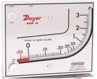
A Dwyer manometer
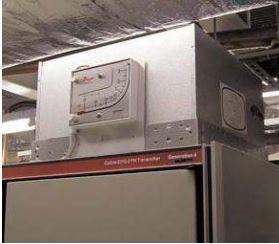
Monitoring airflow
It took me a lot longer to discover the results. The new filters were lasting for years! Even with the increased cost for the filter itself, they paid for themselves over time in several ways:
1. They outlasted cheaper filters significantly. Monthly filter cleaning/changing was history.
2. It virtually eliminated reduced minor problems caused debris in the cabinet.
3. It reduced maintenance man hours, saving me hassle and saving money for my clients.
All in all, a pretty good deal!
Would you like to modify your transmitter like I did at your site? It is not that hard to install. You might even consider modifying the instructions below for other makes/models of transmitters.
Parts List
1. Standard Air Filter Frame – 20×20 Inches – Grainger # 6B840 or equal
2. Air Filter – 20x20x12 Inches – MERV 14 / 95% or better
3. Manometer – Dwyer – Model 25
Aside from some basic hardware, that is all you need. Now, let us put it together.
Construction Notes
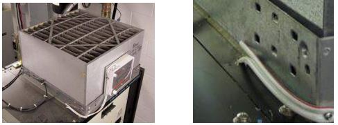
1. Start by preparing a filter frame. Attach a piece of aluminum, centered on one side of the frame to which you will mount the manometer. This need only be larger than the manometer (I suggest using pop rivits so as to not intrude on the inside of the frame thereby preventing filter insertion).
2. Using 6-32 hardware, mount the manometer on the aluminum. Keep the mounting screws level, as it is important that the device be level. Be careful to ensure the screws are just long enough to mount the manometer and not interfere with the installation of the filter itself.
WARNING!
Do not add the gauge fluid at this point!
3. Remove and discard the transmitter’s old air filter. If there is an expanded mesh fan guard, discard this as well. It will add about .1 inch of static pressure.
4. Lay the filter frame on the top of the transmitter, centered about the intake fan area. You may have to offset this a bit if you have conduits, etc., connected to the transmitter’s top. Using a pencil, mark the top of the transmitter along the inside and outside of the filter frame.
5. Lay a bead of RTV (Room Temperature Vulcanizing) or other suitable adhesive/sealant, between the lines on the transmitter top. There is no need to attach the frame using mechanical fasteners –however, you do want to make sure that the frame to transmitter connection is air-tight.
6. Carefully using the marked lines on the transmitter, set the filter frame on the transmitter top, press it down, wipe off the excess RTV and come back in a hour or so (check the setup time on the product used).
Adding the Manometer
7. Make sure the manometer is level; adjust as required. The level indicator on the lower right of the manometer will assist in the process.
8. Now that the frame and manometer are attached to the transmitter you may now add the red gauge oil. Start by adjusting the calibrate knob (on the lower left of the meter face) to the middle of its range. Then carefully pour the oil into the device.
(WARNING – do this slowly as it is easy to add too much)
9. When you have reach the point where the oil is just visible on the scale: STOP! Then adjust the device for a “0” reading.
10. Discard all but about three feet of the supplied manometer hose.
11. Separate the parallel hoses so that you have one long piece (about three feet) and one short one (about one foot).
12. Connect the hoses to the top of the manometer with the long hose on the manometer input (Low) and the short one to the other connection.
WARNING!
The transmitter must be OFF to perform this next portion.
13. The long hose must penetrate the top of the transmitter and enter the space below the filter but above the fan. (Since the goal is to sample the pressure drop across the air filter, you do not want to sample pressure under the fan but rather over it). I typically drill a hole matching the diameter of the hose in the transmitter top, on the back side of the newly installed filter frame.
14. From the top of the transmitter, drill a hole in the back corner of the fan housing, below the lip that used to hold the steel rod or expanded mesh assembly that supported the foam filter.
Note: When drilling these holes:
- If you have a helper, have them hold the intake of a powerful shop-vac so that the shavings do not create a problem.
- If you are working alone, use cardboard, plastic sheeting, gaffers tape, etc., and create a method whereby metal shavings will not get in the transmitter.
15. Push the long hose through the transmitter top, then into the fan housing. You want it to extend about 3 to 4 inches into the space, under the lip, securing it with some more RTV. The end of the hose must be secured and should be dressed in such a manner that it is parallel to one of the side of the transmitter fan housing to avoid picking up the turbulence from the fan.
16. If your “hose-holes” are larger than the hose, you may wish to seal them with more RTV.
17. Dress the hose from the point that attaches to the manometer down along the side of the device and then to the point where you have entered the fan housing. Remember not to cut the foot-long portion of the hose (this will sample the air pressure within the room, out of the way of the actual filter intake turbulence. You may secure this with small clamps or a dab of RTV.
The Air Filter
18. Set the Air Filter in the Frame. You will not require any fasteners as the filter’s weight will keep it in place.
19. Use a felt marker to write the filter’s installation date next to the manometer. This is important as the only way to tell when the filter needs changing is by measuring the pressure drop on the man-ometer. Trust me – you will be tempted to change this filter more often than necessary.
20. Turn on transmitter filaments and note initial pressure drop across filter. Depending on the dynamics of your location, fan type, speed, elevation etc. this reading will vary. In this area, we usually seem to start with a reading between .2 and .25 inches. You may wish to add this reading to your installation date note. (Some manometers also come with an adhesive marker to mark the starting point on the manometer scale.)
Enjoy a Clean Transmitter!
That is it. Pollen, exhaust carbons, dust, bugs, etc. now will remain on the outside of your transmitter.
If you started out with a nice clean transmitter, you will, in short time, notice the dramatic improvement in that much of the transmitter cleaning will become a thing of the past, perhaps with the exception of wiping down some high voltage insulators.
The manometer will tell you when it is time to change the filter by measuring the pressure drop across it. Check the manufacturer’s rating on the filter you use for the point that the filter should be changed. You may wish to mark this on the filter as well to remind others when it is time to re-order. For our setup, the factory recommends changing filters when the static pressure reaches 1.5 inches. In practice, I do not wait that long – and still get long filter life.
Can You Get Even Cleaner?
By the way, if you have another make/model of transmitter, you can adapt this project and reap similar benefits.
For those of you who want to have a really clean plant, consider the installation of a blower system that creates a positive pressure within your transmitter building and pre-filter the air using the same filters as you did for this project.
If you have any questions on how to make this work or pictures showing the various steps, feel free to send me an email or give me a call at 206-947-6115. And, suggestions for improvement are always welcome.
– – –
Clay Freinwald is a long-time part of the engineering community in Seattle, WA. You can email Clay at k7cr@blarg.net