

Exploring the Viability of Second Adjacent Channel LPFM Waivers

[September 2011] The FCC announced plans to open an LPFM window in “Summer 2012.” Under the mandate of the Local Community Radio Act (LCRA), the Commission was directed by Congress to make it easier to file for LPFM licenses. A Third Further Notice of Proposed Rule Making was the result, and new rules and procedures are expected to be issued prior to the window opening.
For those hoping the LCRA will lead to more LPFM stations, a key question is: Will the FCC rewrite the Rules to allow contour maps, as well as stacked and directional antenna array techniques? Otherwise, second-adjacent channel proposals will be quite daunting, if not impossible.
Some of the issues that face the second-adjacent channel aspirants are described here as set forth in this case study, developed for Annapolis, Maryland.
Outside of the Umbrella.
The best place to put an application for a new LPFM is “outside the umbrella.” That is, the “umbrella” is the area inside the full service FM station’s protected coverage contour. For a Class-B station; it is 54 dBu.
For short-spaced stations, it is possible for the LPFM station to be compliant with the present +40 dB U/D [Undesired/Desired] overlap requirements if it can be shown that those contours do not touch.
Under the Ambrella
On the other hand, when the primary contour of the protected station is penetrated by the location of the LPFM station, it is said to be “under the umbrella.” This requires protection methods and strategies that are not in the FCC Regulations for LPFM at this time.
However, there are strategies that have been used successfully used for new FM Translator and Booster Stations.
Parity of Signal Strength
With second-adjacent channel short-spacing, care should be taken to assure that the contour of the second-adjacent full service station is at parity with the 60 dBu service contour of the LPFM station at the point where they touch.
As a matter of good practice, it is desirable to avoid clashing with second-adjacent signals above 90 dBu at the LPFM’s 60 dBu contact points. Otherwise, the LPFM station may get drowned out at the rim of its service area by its strong second-adjacent neighbor.
Vertical Control of the Interfering Contour
A mechanism to put an FM translator station under the “umbrella” has been to prove that the interfering contour did not hit the ground, or residential apartments in high rise buildings.
Roofs of nearby tall buildings also have to be protected because it is possible for someone to take a radio to the roof in order to listen to it in the cool night air under the stars in peace and quiet.
It is not certain at this time if the FCC will allow the 40 dB Undesired/Desired signal ratio for LPFM if the interfering contour can be elevated off of the ground by using vertically stacked arrays. According to Footnote 12 on NPRM #FCC-11-105, page 3:
Compare 47 C.F.R. § 74.1204(d) and 73.807. See also Third Report and Order, 22 FCC Rcd at 21934(translator applicants can often protect second- and/or third-adjacent channel authorizations and pending applications using a flexible contour-based protection methodology while LPFM applicants face substantially greater difficulty in meeting strict minimum distance separations to authorizations and pending applications).
Stacked Antennas
The current regulations do not allow composite or stacked arrays to be used for LPFM.
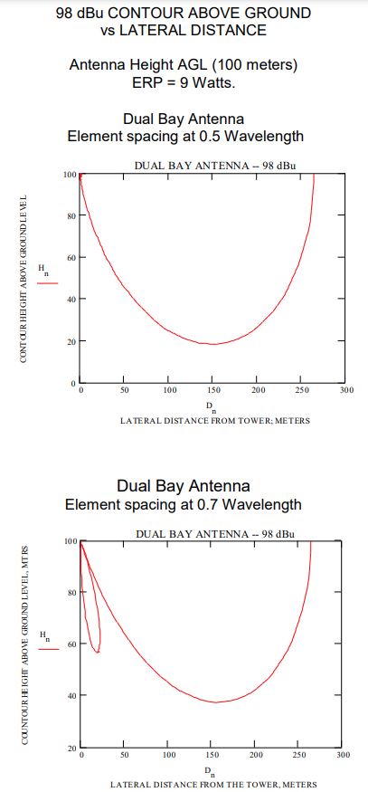
Such multi-bay, vertical stacked arrays compress the vertical cross section of the radiation pattern into more of a pancake shape. Such signals are directed more to the horizon and away from the ground and are effective at heights above 100 meters HAAT (Height Above Average Terrain).
As an example; let us consider the 58 dBu contour of a station to be protected. This signal strength is at the tower site of the LPFM station. The current 40 dB U/D criteria requires that the LPFM 98 dBu contour cannot reach the ground.
The key considerations are as follows:
- The LPFM station will have to operate at a reduced power of 9 Watts ERP at 100 meters in order to maintain the equivalence of 100 Watts at 30 meters HAAT.
- A 2-bay antenna stack would be required to keep the +40 dB U/D contour (98 dBu) at a minimum altitude of 10 meters off of the ground.
- A single-bay antenna cannot do the job. The mitigating factor is the vertical plane profile of the antenna. It is slant distance and the antenna’s vertical plane characteristics that play the major role for signal strength close to the tower.
- An element spacing of 0.5 wavelength is a standard “off the shelf” configuration. A dual-bay antenna with 0.7 wavelength element spacing is very likely to be a special order item, and it will be more expensive. However, it will have a tighter vertical profile.
The following graphs show the how utilizing such antennas can result in more favorable options for the siting of an LPFM station.
Vertical Plane Profiles
The Vertical Profiles of single and 2-bay dipole antennas illustrate the ability to control and direct the signal in the vertical plane. The single bay antenna vertical plane profile resembles a torus or a doughnut.
The two-bay radiation profile in the vertical plane is that of a flattened doughnut where by more signal is concentrated toward the horizon, and diverted away from the ground.
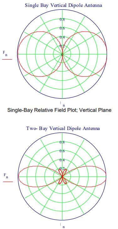
Two-Bay Stacked Array Relative Field Plot, Vertical
Plane, with 0.70 Wavelength between bays,
A Quick Case Study
The map on the next page shows a hypothetical LPFM for Annapolis, Maryland, under consideration at 104.7 MHz.
The proposed station site is located well inside the 54 dBu contours of Class B Stations on 104.3 and 105.1 MHz for WZFT and WAVA-FM. The signal strengths from the Class B stations are in 60’s at the contour contact points as shown on the map.
LPFM Study
104.7 MHz
Annapolis, Maryland
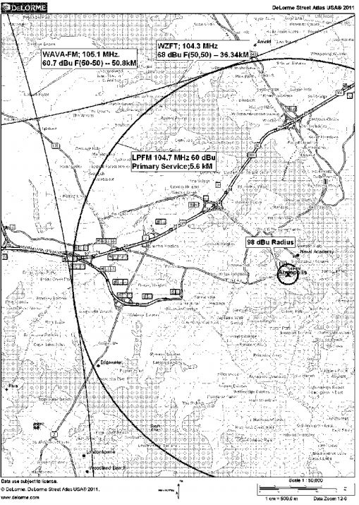
The proposed LPFM station will not get overwhelmed at the rim of its coverage area by the second-adjacent channel stations; WZFT, in Baltimore, Maryland and WAVA-FM, Arlington, Virginia.
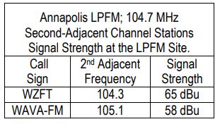
However, the LPFM station must protect the weaker station in the vicinity of its antenna-transmitter site. The weaker station is WAVA-FM. The predicted F(50,50) field from WAVA at the LPFM site is 58 dBu.
- Install a multi-bay antenna on a very tall tower. Diameter of the 98 dBu contour is 264 meters, at 9 Watts ERP (see map).
- Prove the population within the 98 dBu contour is zero.
The 40 dB U/D contour is 98 dBu, and it must be mitigated at the LPFM transmitter site in one of two ways.
Normally, the radius of the 98 dBu contour is about 880 meters at 100 Watts ERP.
This is a possibility if the tower is in a large industrial, non-residential, area or tower farm. The 40 dB U/D contour can be reined in by going higher on the tower and reducing power to maintain facility equivalence.
Will the FCC enable these measures in the new rules? That remains to be seen.
Conclusions About Going Under the Umbrella
If the LPFM station is in-between two mutually fourth-adjacent stations, then the LPFM has two second-adjacent neighbors on the dial.
This means the weaker of the two neighbors must be protected.
The 40 dB U/D protection threshold may be low enough to the point of invoking expensive protection measures.
- Higher antenna position on the tower, at reduced power.
- Multi-bay antenna.
- Proof that the population within the U/D contour is zero (i.e., swamp, industrial park, rail yard, tower farm, etc.)
- Look for another channel with second adjacent neighbors that have stronger signals strengths at the LPFM transmitter site.
- Any combination of the above.
If you are fortunate to find more than one candidate frequency, then chose the channel that has the second-adjacent pair with the strongest “second place” signal.
A stronger adverse contour is easier to protect under the U/D ratio concept. Avoid second-adjacent channel signal strengths below 60 dBu, as these are very difficult to protect with U/D measures.
Installation Complexity Issues
For an LPFM site inside the primary contour of a second-adjacent station, the ability to lift the interfering contour off the ground is necessary. A multi-bay antenna on a tall tower with space available at the 100+ meter level and above is required.
The higher antenna height entails more cable, and higher installation costs for that cable as well as that for the antenna.
The only payback is smaller transmitter power requirements due to height, and the added gain of the multi-bay antenna.
Rent also increases according to height and the antenna’s aperture A two-bay FM Broadcast Band Antenna requires a tower space of 9 to 12 meters depending upon bay spacing. This also nudges the rent higher.
– – –
ACKNOWLEDGEMENTS, REFERENCES:
Graphs generated by MathCad, PTC Inc.
Maps generated by Delorme Street Atlas 2011.
OET Bulletin #65; Office of Engineering and Technology.
NPRM #11-105, page 3; footnote #12
Jeff Macris, Annapolis Maryland; jrmacris@hotmail.com FCC Radio Tools; www.fcc.gov
FCC Rules; §73.310; Field at 1kM for 1kW ERP.
FCC Rules; §74.1204; Protection of FM Broadcast, Translator and LP-100 stations.
– – –
James W. Pollock, P.E., is a consulting engineer based in Mt. Laurel, NJ. He can be contacted at: jim@jimpollock.net