

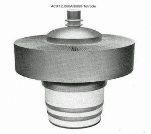
The 4CX12,000A Story

[July 2025] Even as we move further and further away from using tubes – especially power tubes – in transmitters in favor of solid-state products, the history of those power tubes and how their development helped the broadcast industry grow with reliable power amplifiers. Reid Brandon is back with a look, this time, at the 4CX12,000A.
I never realized what was involved with developing a tube much less what was contained in the data sheet for it but after starting work at Eimac I found myself involved in both.
In my previous employment I had access to a large Eimac binder filled with data sheets. I built a linear amplifier around an Eimac tube and read Bill Orr’s articles in ham magazines where one could appreciate the frequent contributions Eimac made to the technology. Developing new tubes appeared to me to be straightforward and no one spoke of faulty tube design.
The 4CX12,000A/8989 was the first product that I was involved with and the experience turned out to be more than I ever expected.
The process actually required considerable work besides writing data sheets. Things like communications between co-workers, to and from customers, and even dealing with sales representatives in foreign countries were in my future.
HIGH GAIN AND EFFICIENT
The 4CX12,000A/8989 and 4CX20,000A/8990 actually marked a refinement in the way Eimac had been making tubes since the 1960’s, the 4CX5000, 4CX10,000 and 4CX15,000 were all well-accepted as reliable tubes used in numerous applications.
However, compared to the common hairpin-shaped filaments, these new tubes had a cylindrical mesh filament with lower inherent inductance, and the rigid construction allowed closer grid-to-filament spacing which improved gain at VHF. Shorter control grid and screen grid structures reduced internal inductance and capacitance which improved RF circuit performance.
Mechanically, the new tubes were very similar, without handles on the top like on existing Eimac 10 and 15 kilowatt tubes. They used Eimac’s new wavy-fin design in the anodes for improved thermal transfer with less noise compared to straight cooling fins. Their qualities of high gain and efficiency made the 4CX12,000A and 4CX20,000A good choices for the new transmitters that were then being introduced.
Both tube types were assigned EIA registration numbers consecutively in 1979, type 8989 for the 12,000A and 8990 for the 20,000A.
The market was growing and manufacturers were busy developing new equipment for it. Actually, the 4CX12,000A/8989 was put into production several years after the 4CX20,000A/8990 due to greater demand for new FM transmitters at 20+ kW.
RELIABLE IN USE
From its introduction the 4CX20,000A proved to be exceptionally reliable in numerous broadcast stations, eventually some of them achieving 40,000 hours of service, perhaps helped by Eimac’s Application Bulletin No. 18 “Filament Voltage Management”1 published by Bob Artigo.
It was probably felt the 4CX12,000A would perform as well and it would be a great choice for new FM transmitters at lower power.
Harris and Broadcast Electronics were competing for the large opportunities in the US as a result of new FCC high power licensing. I made numerous trips with George Badger, marketing manager at Eimac, to Quincy IL where we visited both Harris and Broadcast Electronics. GE Larcan was phasing out tube transmitters while Continental Electronics was attempting to squeeze as much power out of the 4CX15,000 in their ex-Collins 816R design as they could (covered in another of my stories).
GAINING MARKET SHARE
In 1984 Jim Pickard, an ex-RCA tube engineer, was at Harris Quincy and in the early stages of developing a new FM transmitter around an RCA tetrode.
The existing Gates FM-10H3 had been designed by Bill Hoyt. It employed a 4CX10,000D and was later revised to use a 4CX10,000J driven by a 4CX300A. Its lack of screen current metering of the PA tube was noted as a deficiency.
The RCA tetrode Harris was considering was priced considerably higher than an 4CX20,000A/8990. RCA’s tube socket was also complicated and not available as a common item while Eimac was producing complete sockets with integral screen bypass capacitors that had been developed for Eimac FM cavity amplifiers that were being produced for OEMs.
Larry Cervon, an ex-Harris employee, had formed Broadcast Electronics and captured market share for new FM transmitters leaving Harris trying to catch up. Geoff Mendenhall, BE’s chief engineer, had designed the Eimac 4CX7500A into their 10kW FM transmitters. The unique folded-transmission line anode circuit BE developed eliminated conventional plate blocking capacitors, a failure prone item.
GETTING TO REALLY KNOW THE PRODUCT
My initial job assignment was to study under Bill Sain, Sr. tube design engineer, where I was to learn the way things were done at Eimac. I would then transition into marketing and become an applications engineer, the position that was vacated when Bill Barkley retired and went to Econco in 1983.
One of my first assignments in marketing was preparing new data sheets, and the prototype 8989 was my very first. I recall purchasing a set of French curves to draw the constant-current curves in pencil from the data points, which then would be sent to an artist where it would be reproduced in ink for publication.
Eventually I would retire after creating and revising dozens of Eimac data sheets.
I inherited a preliminary data sheet for the 4CX12,000A/8989 showing a filament voltage of 7.5 Volts. It had been prepared in 1981 using a DEC computer with a large noisy dot matrix printer. In 1984 I received a new PC using MS-DOS and that was a great improvement over the DEC with its complex operating system which I never learned.
The first National Association of Broadcasters show I attended was in 1984 when Bill Orr accompanied me and showed me how to set up the booth, place mechanical sample tubes on exhibit and load racks with data sheets for hand-outs.
ENTER ITELCO AND BE
An Italian broadcast firm named ITELCO showed great interest in the 4CX12,000A/8989.
Dr. Fumi met us at a NAB show along with Sergio Centroni, the Eimac sales representative for Italy who informed us of a requirement for a large number of 10 kilowatt FM transmitters in Sweden. ITELCO initially was considering using a Siemens tetrode but that firm suddenly discontinued making high power tubes, creating an opportunity for Eimac and a sample 4CX12,000A/8989 was sent to ITELCO for evaluation.
Swedish Telecom then standardized their country-wide network to operate only with 4CX12,000A tubes. A representative from Sweden even contacted Eimac to gain assurance that future replacement tubes could be procured direct which Eimac agreed to.
Broadcast Electronics won a contract to supply Swedish Telecom with their FM-10A transmitters modified to use a 4CX12,000A/8989, replacing the 4CX7500A.
SOLVING A TUBE PROBLEM!
Then Sergio reported a tube failure at ITELCO where the sample tube was arcing and unusable.
Sergio contacted Werner Brunhart of the Eimac Salt Lake City plant; he was in Europe at the time and agreed to go to Italy and help with the problem.
Werner’s background as an ex-Machlett tube engineer helped solve the problem. I recall a phone call he made to San Carlos giving his observations on the problem2. Werner confirmed the tube had internal arcing at full power and he asked for a cross-sectional drawing of the 4CX12,000A/8989.
In those days a FAX machine was all that was available (the Internet was in its infancy) so there was a delay before he was able to examine the drawings. But when he did, he saw the need for an internal shield at the bottom of the anode which would reduce carbon deposition from the filament on the inside surface of the ceramic envelope.
Eimac called this a “gunk shield.” Why it was not incorporated in the original design remains a mystery.
After the anode improvement 4CX12,000A/8989’s performed well at ITELCO with no arcing and subsequently Swedish Telecom placed an order for a dozen or more transmitters split between BE and ITELCO.
ANOTHER TUBE PROBLEM ARISES
Due to the geography in Sweden, many of the country’s transmitters were located at elevation in remote places where the only access in winter months was using helicopters.
Due to high service costs Swedish Telecom had included in their contracts with BE and ITELCO a penalty clause for transmitter failures (including the tube). After about a year Swedish Telecom reported short tube life, in some cases as little as 6 months tubes began to lose power.
A comprehensive study listing all the sites with the accrued tube life in hours at each location was prepared and it clearly showed poor tube life in virtually every transmitter.
Eimac’s engineering staff took temperature measurements of an 4CX12,000A/8989 filament in a bell jar using an optical pyrometer. It showed something around 2100 degrees; by comparison the 8990 with its excellent filament life was 1800 degrees so it was obvious the 4CX12,000A/8989 filament temperature was too high.
COOLING THINGS DOWN
It was calculated that if an 4CX12,000A/8989 were operated at a filament Voltage of 6.5 Volts instead of 7.5 Volts the expected life would be around 25K hours or even greater with filament Voltage management.
There were two remedies to this problem: (1) redesign the filament using thinner tungsten wire to reduce the current or (2) reduce filament Voltage in the transmitters using the tube as it was. I was in favor of the first solution but the second solution was chosen because it would avoid having to go through a complex change order. The problem was there are very few small diameter thoriated tungsten wires available and a custom diamond die would be required to draw filament wire to a new diameter. The quickest solution would be to simply reduce the filament Voltage.
After proposing this we learned BE was able to make a change that allowed adjusting the filament Voltage to 6.5 Volts but ITELCO would need to replace the filament transformers. George asked what ITELCO would accept to offset accrued warranty costs at Swedish Telecom. A mutual agreement was made for a number of tubes to be provided by Eimac at no cost and ITELCO agreed to replace filament transformers. Ultimately Swedish Telecom agreed to this proposal and George accepted a no-charge order for 20 tubes.
[the_ad id=”2906″]
A QUICK CHANGE
I immediately destroyed all the old data sheets and had new ones printed showing a filament Voltage of 6.5 Volts.
Ultimately, after all the setbacks, the 4CX12,000A/8989 proved to be a reliable tube. Nevertheless, a decade or so later I learned Swedish Telecom had replaced all their 10kW tube transmitters with solid-state equipment.
That period was a very stressful time for George because, as marketing manager at Eimac, he received the blame for the financial burden associated with replacing the tubes, despite trying to explain to management it was because of an engineering error. (Bill Sain, the tube design engineer had retired prematurely due to health issues so it was never clear why he chose 7.5 Volts. By conjecture, perhaps that was the same filament Voltage of a competitive tube the 4CX12,000A/8989 was intended to replace.)
TUBES START TO LOSE GROUND
In the mid 90’s, after Varian corporate pressure became excessive, George Badger left Eimac to become VP of Svetlana USA until that firm was unable to obtain inexpensive Russian tubes. He then became an employee of Econco, the tube rebuilder in Woodland CA.
Eimac’s annual sales of $50M in 2005 dropped to $32M in 2008 and was close to $25M in 2016; almost a decade later it is likely to be under 50% of that figure. By 2012 all of Eimac’s new tube development capabilities were virtually gone after the last engineering staff retired early or were terminated.
By 2020 sales of Eimac’s 4CX12,000A/8989 were very low due to many FM tube-type transmitters having been replaced by solid state equipment and some stations having tubes rebuilt at Econco.
I suspect Thales will remain as the last world-class tube company still developing new high power electron tubes for scientific applications.
THE END
After Eimac had relocated Eimac to Palo Alto in 2007 the show tubes had not seen the light of day because the ex-Varian management had no desire to show the range of Eimac products in the facility on Hansen Way (home of Microwave Power Products where Eimac tubes are now being made).
After learning the show tubes were to be scrapped, I managed to save the original 4CX12,000A prototype – the very tube I had been trained on some 25 years prior! It is not really good for anything, but it sure reminds me of a very productive period of my life.
In recent years, fewer and fewer transmitters utilize the 8989 or 8990. For those that are still operating, rebuilt tubes are getting even more scarce – and expensive!
With no other applications for a tube of this size and the advent of solid-state technology, sadly the 4CX12,000A is just a distant but interesting memory in the minds of a few individuals.
– – –
Footnotes:
- Eimac Application Bulletin AB-18, original version March 1982 by Bob Artigo, https://www.worldradiohistory.com/Archive-Catalogs/EIMAC/EIMAC-Extending-Transmitter-Tube-Life-1982.pdf and revised 2010 by Reid Brandon: https://www.g8wrb.co.uk/data/Eimac/AB18.pdf
- Werner had a way of describing matters in a sharp manner. When asked to comment on the ITELCO trip his response was something like: “A wildass engineer in San Carlos made the first tubes without an anode skirt so the ceramic was building up internally and arcing. I picked up the phone and called Bob Tornoe to tell Eimac to change the %#*& tube (explicative omitted)”.
– – –
Reid Brandon (W6MTF) worked for Eimac’s tube division for 27 years, until his retirement in 2013. This is his fourth article in a series looking at some of the famous and/or special tubes that were produced over the years by Eimac. Contact Reid at rfburnz@yahoo.com
– – –
Would you enjoy more articles on broadcast history like this?
Click here for a quick (30 seconds) sign up form for the one-time-a-week BDR Newsletter.