

DA Q&A: When Antenna Monitor Readings Go Strange Part 2 – Checking Out the System

[June 2012] Do you maintain a directional antenna? If so, this series is designed to help you. If you have a question, send it on to Kurt at the address below.
We are discussing what to do when the antenna monitor suddenly gives non-standard readings, and how to find what is the problem and where it is located in the transmission system.
Previously we began the process by verifying that the sampling system is not giving a false indication. It is now time to go through the antenna system itself to try to find out what is wrong and why.
Stay Legal
Once you have established that the antenna monitor is reporting accurately, the first task is not to turn a crank.
Your first task is to stay legal – to make sure your system is not putting more RF than permitted.
A quick run out to the monitor points will show exactly what is being transmitted. Depending upon the problem, simply lowering the transmitter output until things are resolved may be the fastest way to bring you within radiation limits.
Check them. Log them. Now, it is time to get on with inspecting the system and repairing things.
Looking for Clues
If the parameters for all the towers have changed a similar amount, the problem may be associated with the reference tower.
On the other hand, if one particular tower’s parameters are much further from the licensed than the others, this may be the possible source of the problem. However, arrays which have a high degree of mutual coupling between elements can be difficult to determine which tower is the problem, because as the current amplitude/phase change in a given element, all others will change.
If your system has separate patterns or a different number of towers for Day and Night modes of operation, checking each pattern’s parameters will narrow down if it is common to both patterns, or particular to one.
Inspecting the Components
At this point, you should perform a visual inspection of the suspect tower(s) and the phasor. Some things are easy to see, as soon as you open the cabinet. Others are not so obvious.
A top: take an infrared thermometer with you to “see” the things you otherwise would not see. Use your camera to document what is inside the cabinet, and the position of movable items.
It is important to check all of the components and connections for any sign of heating or arcing, or where a connection that has come loose. Also, check any RF contactors for proper position and good connections.
Typically fixed coils do not change unless there is a connection problem with the tap connected to it or a problem with the insulated bars holding the winding.
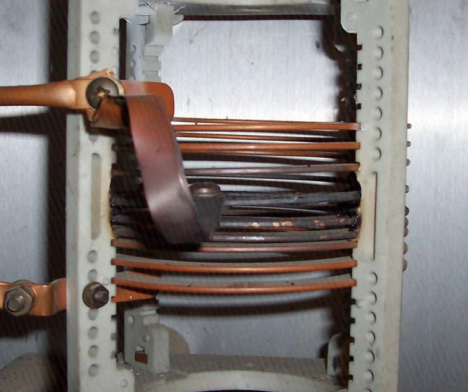
and things got a little overheated
The tap on this coil became loose and things got a little overheated
Often seasonal temperature changes cause the expansion/contraction that loosens connections.
Variable coils can experience an open or high resistive connection with the roller assembly and/or shaft contacts.
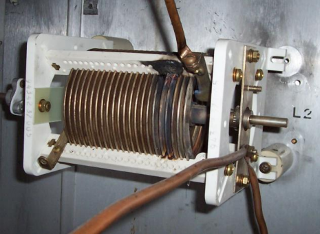
Notice the melted frame.
Something happened to this coil. Notice the melted frame.
A small turn back and forth may be done to see if the contacts change. Note: It is always a good idea to mark the location of all taps and rollers prior to moving them.
Evaluating the Capacitors
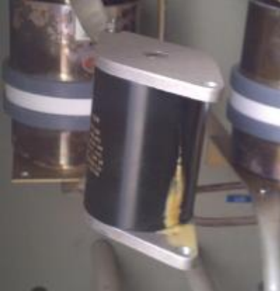
Capacitors are not always as easy to spot when there is a problem. Internal shorts or opens are not always accompanied by physical damage.
In extreme cases mica capacitors will crack with excessive current/voltage. Some leak.
A careful feel of the capacitors – after you have removed RF from the antenna – will verify whether or not there are cracks.
Removing each capacitor from the circuit and measuring with a capacitance meter or any impedance measuring device will verify the capacitor is within its rated capacitance range. If you do not have access to equipment to measure the capacitance or impedance, a DC Ohmmeter can be used to at least verify the capacitor is not shorted.
Another diagnostic tool is to note the color of the capacitor. Alan Alsobrook recently offered some tips on troubleshooting large capacitors.
The same procedure can be used for vacuum capacitors. Glass vacuum capacitors can show internal signs of arcing between the plates.
Look for Shorts to Ground
In addition, check around the antenna tuning unit output at each tower as well as the tower base insulator for anything that could short to ground or otherwise change the impedance.
Another check is to use an operating impedance bridge (OIB) to would measure each tower’s output from the phasor and see how it compares to the characteristic impedance of the transmission line – typically 50 Ohms. A caution, however, is that unless you have previous data for these numbers, you may not know if it has changed dramatically. Also, as the array parameters change, these numbers will change.
Still, finding a very high or a very low impedance may help determine which tower(s) have a problem.
In some cases, you may find the array parameters are not out of tolerance, although the input impedance match to the transmitter has changed. This may indicate the input common point circuitry that has a component issue or a problem with the line/switching prior to the network.
Coax Damage?
If all the phasor and antenna tuning unit (ATU) components appear to be ok, there could be a transmission line problem. Especially in wet weather, all it takes is an off-road vehicle in the wrong place, and the coax could be damaged.
With both ends of the line disconnected, a simple DC check for an open end then with the opposite end shorted, will at least verify the line has continuity and no internal shorts.
After all these checks, it is quite likely you have narrowed down the potential problem components. Now it is time to decide how to go about fixing the problem.
– – –
Kurt Gorman, President of Phasetek Inc., is a second generation engineer and phasor manufacturer. If you have a question about directional antenna systems, you are invited to ask Kurt. His email is: kurtgorman1@earthlink.net