

The Convoluted History of CCA or, How the Grounded Grid Went South

[September 2021] Broadcast transmitters are always an interesting topic. Over the years, the industry went from one or two manufacturers to a dozen, and now are back to a handful – leaving transmitters installed in many places, with newer engineers sometimes wondering where they came from, and why. One of these manufacturers, CCA, has quite an interesting history. Phil Langston recalls:
In the early 1960’s several engineers who had previously been working at RCA’s transmitter manufacturing plant set out on their own starting several broadcast equipment companies in the area around Camden and Philadelphia.

Bernie Wise
One of these was Bernie Wise, a former RCA engineer who had started ITA (Industrial Transmitters and Antennas) in 1957 to manufacture transmitters and other gear for education stations and under contract for Collins Radio Company.
Although ITA sold a lot of FM transmitters through Collins, painted in Collins’ colors, the instability of the tetrode design caused the company troubles. (Collins was forced to replace many of the ITA units when they built the 830 series.)
By 1962, the relationship between Bernie Wise and Walter Annenburg (Publisher of TV Guide) fell apart. Annenberg sold ITA and it went out of the broadcast business in the early 1970s.
THE FIRST CCA
Shortly after he was ousted from ITA, Wise formed CCA Electronics in nearby Gloucester City, New Jersey.
Wise’ main selling point was that CCA provided a more affordable transmitter line than the major manufacturers at the time such as RCA, Collins or Gates. CCA became a common solution for the many smaller market stations which were popping up across the country.
CCA’S BASIC DESIGN
CCA’s AM transmitters, like most others of the time, used a plate-modulated design. The models used a “D” designation, as Bernie had used A, B, and C at ITA, his previous company.
CCA AM-1,000D
They worked well for many stations, and were fairly reliable, with some still in use, especially on the Ham Band. Models up to 50 kW were built, the AM-50,000D, some as “dual” units so the station would not have to go off air for a single parts failure.
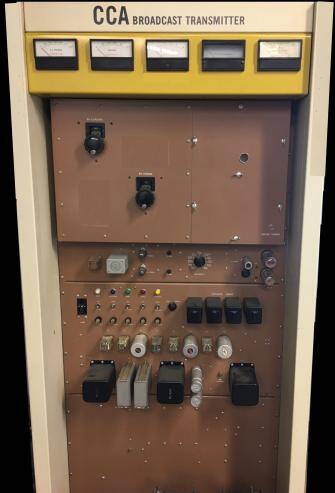
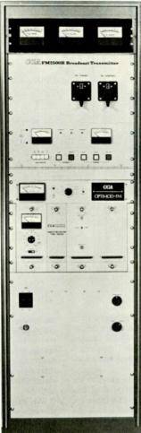
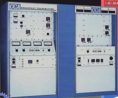
CCA became best known for their FM’s which used a cathode driven (grounded-grid) triode for the final power amplifier. This was a relatively simple and low-cost design. It had the advantage of not requiring neutralization circuits and typically utilized a single high voltage supply.
CCA FM-25,000E
Many other manufacturers also started their FM product lines with grounded-grid designs but by the 70’s most had moved to tetrodes. Lots of FM transmitter began being sold as “single tube solutions” as solid state exciters or driver stages could be used to drive tetrodes with higher gain.
Nevertheless, for the smaller “mom and pop” FM’s the grounded grid was still a good fit and CCA along with several other companies supplied them for the next couple of decades.
COMPETING AGAINST COPYCAT
Among those other companies was CSI where Bernie Gelman was producing similar products.
They were so similar that it led to at least one lawsuit and a degree of animosity between the two companies that became legendary.
While I was at CCA in Fairburn I was told of one law-suit in which the large, hand drawn schematics of a CCA and CSI transmitter were laid on top of each other on a light table in front of the court and they matched exactly – including a couple of misspellings.
Unfortunately, which side prevailed I do not recall.
Another company was Sintronics which listed Gerald “Jerry” Meier as Product Director in the Broadcast & Cable Magazine Yearbook’s manufacturing directories for the late 70’s.
NO MORE BERNIE
By the time I began my broadcasting career in Georgia in 1976, Bernie Wise had left CCA and would found Energy-Onix two years later.
“The New CCA,” which was now in Cherry Hill, New Jersey, was represented in the south-east by Broadcast Communications Associates. BCA was operated by Ron Baker and provided engineering services as well as sales, even turn-keying an entire station if needed.
The company advertised that it could build FM transmitters from 1 to 80 kW, and even had a budget line, “R,” such as the 2500 W “Little Rascal,” delivered in a 5’7” rack frame or, later, a half-rack frame, dubbed the “Li’l Rascal.”
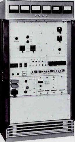
CCA FM-2500R
The Little Rascal
A series of UHF TV transmitters, the TA-xx-BT series was advertised from 15 to 100 kW, but it is not known how many were built.
Around the same time I would occasionally get a mailing from the J.S. Betts Company selling RF hardware and surplus items from a warehouse in Fairburn Georgia about 20 miles south-west of the Atlanta airport. Mr. Betts later either partnered with, or sold his parts business to Ron Baker since the Betts facility later became the home of CCA.
By the 80’s CCA and several of the other smaller transmitter manufacturers were falling on hard times.
And in 1982, the company went bankrupt.
A SECOND INCARNATION
Ron Baker bought out the remaining assets of CCA, as well as CSI and Sintronics moving them to what had been the J.S. Betts facility in Fairburn.
His plan was to continue provide parts and service for the large base of CCA owners which included many of his old customers
Along with the parts and repair requests there was enough interest in new transmitters that he began manufacturing a few new ones under “The New CCA” name. When it appeared there was demand for more than just a few transmitters, full-time assembly people and techs were brought on board.
Chief among them was Jerry Meier who brought his manufacturing back-ground and skills needed for the new venture.
CCA was back.
BRING THEM ALL TOGETHER
What eventually became the CCA FM G (the “G” for Georgia) product line from Fairburn was a hybrid borrowing features from the other companies acquired with it.
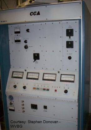
CCA FM-2500G
All the G line transmitters
looked the same
The distinctive waist-high sloped meter panel came from CSI. The control and metering PC boards behind the meter panel looked very much like boards used by Sintronics.
The re-mote control interface also was similar to CSI and Sintronics which used 24 Volt relays. (Old-er CCAs had 120VAC controls that could not be directly connected to the relays on most remote control systems.)
RETAIL DROVE THE SHOW
The CCA product line was driven by the sales department meaning there was a rather large array of FM transmitters to offer customers.
There was an FM-G model for 2.5, 4, 5, 8, 10, 12, 20, 25, and 35 kilowatts. All of the standard FM’s used the same blue main cabinet meaning extra room inside for the low power units and rather tight quarters by the time you got to 35 kW. The control assembly which held the meters was also the same for all FM’s. The meters themselves were all 0-100 μA movements with the appropriate scales inserted for that model.
From the front of the transmitter the only way to tell which model you were looking at was the screen printing on the front panel.
POWER SUPPLIES
Something else that was retained from some of the older designs was a high voltage power supply with a high/low power circuit usually seen in AM transmitters.
In three-phase units this was done by switching the power transformer primary windings form a wye to delta configuration. In single phase transmitters one side of the transformer was connected to the neutral or ground in low power.
Pressing the high power ON button would bring the transmitter up at half power for a few seconds then transition to full power. This was used in place of the resistor step-start circuits used in other manufacturers and provided a quick way to reduce power for initial tuning or trouble-shooting.
THE SAME RF SECTION
The early FM RF section design was unchanged from the earlier ones produced in New Jersey at first.
Later changes were mostly in the IPA stages. Originally a 5CX1500B was used as an IPA in transmitters above 20 kW. Lower power CCA FM’s used an 8122 tetrode and later an 8874/3CX400 triode as a grounded grid IPA. There was also a retrofit kit available to use the 8874 in older units that had used the 8122.
INCREASING THE EXCITER OUTPUT
Initially all FM’s were driven by exciters putting out 10 to 20 Watts.
In Fairubrn a 60, and later a 100 Watt exciter was developed. One of the factors driving the need for a higher power exciter was a new IPA design using Eimac’s recently introduced YU181/3CX1200Z7.
The YU-181 was a “socket-less” triode that mounted upside down. A skirt surrounding the base allowed it to be bolted in its mounting hole in the IPA deck. The pins for the filament and grid connected with small clamp assemblies. Underneath the connections to the anode were held by a hose clamp which also held a chimney to direct air through the tube’s fins.
BUT THE TUBE DID NOT WORK
The tube seemed to work quite well at first but soon more and more were being replaced having failed during the warranty period.
After some investigation by Eimac, they discovered that the failures were due to contaminants inside the tube which were somehow being introduced in the manufacturing process. These tubes were being built in a new facility in the Salt Lake City area. Despite meticulous filtering, some of the ultra-fine mineral laden dust from the nearby dry lakes was finding its way inside the plant and into the tubes.
Eimac’s solution was to shut down the line and move it back to California meaning no new tubes for several months!
FM transmitters already ordered and some almost completed had the IPA sections changed to use either the 8874 or 5CX-1500B. By this time some were being built with a solid state IPA using a 500 Watt Silicon Valley amp.
MORE CONFORMITY
In addition to the transmitter power out levels, CCA offered some surprising options for the input AC.
Most manufacturers of tube-type FM transmitters had options for single or three-phase power up to 5 kW, a few offered a single phase 10 kW. Anything bigger meant you needed to contact your utility or someone selling rotary-phase converters. Yet, CCA offered a special order single-phase FM-20,000G and at least one with a TPO well over 20 kW.
Eventually a three-phase series was labeled “G3.”
These used the same cabinet as the 10 kW AM which was about the same size as two of the standard FM cabinets side-by-side. One side had the RF components and the high voltage transformer with the other side housing the very large filter chokes and capacitors for the supply. The AC mains current needed for 20 kilowatts of RF was above 200 Amperes so these transmitters had to be tested in a separate high power test bay in the warehouse close to the utility power feed for the entire facility.
45 KILOWATTS AND MORE
Another unusual FM product was the “super power” FM-45,000G.
This was a single transmitter, not a combined system, capable of putting out up to 50,000 Watts. This was designed around a triode that, if I recall, was built by Philips for industrial use and was resold by CCA as a “CCA-30,000.” The final stage was driven by an FM-8,000G which could be patched directly into the antenna in an emergency.
CCA FM-45,000G3
from a brochure
I was told that the power limit of 50 kW was due to the power supply and that, theoretically, with a large enough supply the tube would still be well below its maximum specifications with the transmitter putting out 100 kilowatts.
Only two were built. Both purchased by Great American Radio with one in Atlanta for WKLS and the other for WXTB Clearwater-Tampa.
SLIGHTLY NEW MODELS
Fairburn also built newer versions of the plate modulated one, ten and fifty kilowatt transmitters – many modified for the short wave broadcast service.
These were basically original CCA designs with updated control circuits. Solid state exciters were brought on board, with a “GS” or “GZ” model designation. Shortwave transmitters that needed to operate on multiple frequencies used a modified amateur radio transceiver as a synthesizer.
The ham rig was ordered with tighter commercial frequency stability specifications and operated in CW mode basically replacing the crystal normally used to drive the RF stage.
Since the tuning controls were manual-only a laminated chart on the front panel listed the values for the tuning and loading cyclometers for each assigned frequency.
A couple of the modified 10 kW AM transmitters were supplied to the National Institute of Standards for use at WWV.
MY FINAL TRANSMITTER
The last project that I was involved in at CCA, which was also probably one of their last AM transmitter projects, was for WRNO Shortwave in New Orleans.
Their main transmitter, a Harris SW-100 had failed and could not be economically repaired. CCA offered a shortwave version of their 50 kW AM as a replacement.
Like the other CCA transmitters their AM-50,000D was an updated version of the original design which, in this case, was a plate-modulated system using 4CX-35,000C’s for the modulators and PA.
The transmitter built for WRNO needed to operate on two of the shortwave bands at approximately 7.5 and 15 MHz. The 50,000-D PA and RF drivers could not be modified to operate reliably over this wide a bandwidth so the WRNO transmitter had to have an RF section for each band. Large E.F. Johnson type RF contactors were used to switch the modulator between the two RF sections.
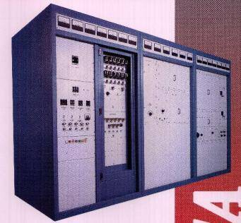
CCA AM-50,000D
from a brochure
The standard 50,000D was big. It used three cabinets that were 4-feet wide and almost as deep and a bit over 7-feet tall. The WRNO transmitter when complete was 16-feet long and nearly filled the high power test bay where it was built and tested. In addition to the transmitter the WRNO system included a large outboard impedance matching network to couple the transmitter’s 50 Ohm output to the WRNO antenna system’s 300 Ohm open-wire transmission line. The transmitter took considerably more time than expected to complete and some work continued after delivery and installation at the WRNO site.
CHANGES IN THE INDUSTRY
By 1997 when I left CCA, the radio business was changing.
After the 1996 Communications Act, many of the “mom and pop” stations that made up most of CCA’s and other smaller manufacturers’ customer base were bought up by the several large conglomerates.
The technology was also changing too. Pulse width and digital step modulation for AM meant that by the end of the 90’s not only was no one making new tube-based AM rigs but actually seeing one used as the main transmitter was a rarity. Tube FM transmitters were still beating solid state in efficiency but with digital radio on the horizon and the costs of recurring tube replacement the days of “big iron” was coming to an end.
CCA struggled on, focusing their efforts on shortwave and export business for a few more years until being dissolved in 2002.

Baker’s CCA went bankrupt in early 2000, and Commercial Communications Associates, an investment group (based in Luanda, Angola) headed by Alvar St. Aubyn purchased the assets. It did not last very long, CCA once again filed for bankruptcy and closed its operations in early November 2002. It owed creditors several hundreds of thousands of dollars.
As the bankruptcy started liquidating assets, six transmitters were in varying states of construction at the time. Several stations paid the bankruptcy trustee a few to get possession of the transmitter, plus additional costs to finish construction. Most leftover parts went to V&J Electronics (two former CCA employees) and Goodrich Enterprises in Omaha, NE.
– – –
A former contract engineer, before and after his time at CCA, Phil Langston worked at CCA Broadcast Electronics as an RF Customer Support technician and then Harris Corporation as an Applications Engineer. He currently is at the Wisconsin Educational Communications Board or ECB.
You can contact Phil at:
phillangston@yahoo.com
– – –
Did you find this article helpful? Would you like to know when more articles like this are posted? It only takes 30 seconds to sign up here for the one-time-a-week BDR Newsletter.