

Solving Some HT 3.5 Troubles

[July 2014] When a station is off the air, the pressure is on to find and fix the problem immediately – or at the least, get back on the air with as much power as possible. Unfortunately, that approach can lead the engineer to overlook the real cause of the problem.
Alan Alsobrook has been there (and has the T-shirt). He explains how he got back on track to actually fix the underlying problem.
If you are caring for one of the lower power Harris (now GatesAir) HT transmitters and you have not seen the problem I will describe as yet, you likely will.
The good news is you can prevent it with just a couple hours of work.
Off the Air
As usual, the process started with a call one afternoon: “our station is off the air.”
This particular transmitter was a 1992 model HT-3.5, now in service for about 20 years. A quick check with the remote and sure enough it was clear the transmitter was down and would not be enticed by my commands to come back up.
To be honest, I was semi-expecting trouble of some sort soon as the tube was approaching end of life. Still the tube was making full power, I was only expecting to hear the power was dropping off and would not come back up – not that it was dead in the water.
Of course, when the tubes in these units get a bit long in the tooth, you will occasionally see a screen overload trip. Normally, you can recover quickly by turning off the APC and backing down the power a bit.
Quick Diagnosis – or Not
On arrival at the transmitter site, I immediately saw the screen overload indications.
Yet, even trying the local controls, the transmitter still did not want to come back up at all. In fact, it was not until I had backed the power down to less than 20% that it would hold up on the air. At this point I decided that had to be good enough for prime time, and I planned to change the tube after midnight to minimize off-air time.
You likely have already figured out that I was making a basic troubleshooting error by deciding the problem was the tube kicking the bucket and not actually checking for the cause of the trouble.
A Second Pass at Repair
During the late night return trip, after shutting the transmitter down and taking all safety precautions, I cleaned the transmitter up and put in the new tube.
By the way, I normally do my major cleanings with each tube change. But this previous tube had a long life: 128,652.7 hours – or over 14.6 years of 24/7 operation. So the cleaning process did last until about 5AM.
However, when I started to tune the transmitter – surprise! – the inability to make full power was still there. As a result, I really did not have very much time left for troubleshooting before the morning crew needed to be up and operating. Thus the decision was made to continue at low power for another day.
A More Detailed Exam
Upon returning, finally I started a proper troubleshooting procedure. Looking at the meter readings it did not take long to spot a problem.
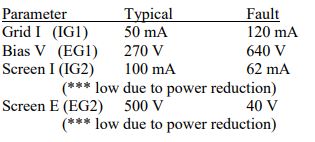
We might well call these last two readings “the clue.”
Looking back at the transmitter’s history it was actually very easy to spot the trouble. You may have heard this one before but it bears repeating: as part of your documentation, keep a history of the transmitter meter readings. This experience proves why.
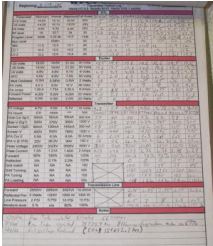
Some of the readings stood out from the normal numbers recorded over the years.
The Answer Was Already There
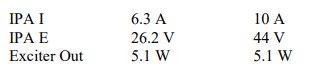
Carefully noting the deviations from normal, the voltage to the solid-state IPA was way up.
This condition caused excessive power output from the IPA, seriously overdriving the grid of the tube. Luckily the tube showed no signs of damage from being overdriven, but it easily could have killed a good tube.
Now, focusing in on the IPA as the source of the trouble, it did not take long to determine that the series regulator was shorted allowing the full output of the IPA power supply to hit the IPA.
Locate and Replace
Now that I knew where the problem was, it was time to start repairs. That included finding and accessing the IPA regulator circuit.
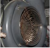
After a bit of looking, the regulator was located mounted directly behind the IPA module, in the intake airflow of the PA blower.
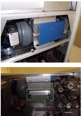
When I first looked at the mounting position it seemed like it would be rather difficult to access and repair. When in reality it was not that difficult at all.
By simply removing the IPA assembly from the transmitter and then removing the screws securing the support panel it was attached too, gave quick access to the IPA.
The down side is that the wires attaching it are not easily disconnected and it is easier to repair the regulator while it is still connected.
To do that I separated it from the support panel and stood it up on a rail and slid it to the side, locking the heatsink securely into transmitter back frame.
![]()
To start the repair all of the MJ15015 transistors were removed from the heat sink along with the LM 317 regulator. Of the four transistors, one was found shorted and another was found to have an open base.
One thing I found that turned out to have major importance was learning that the heat sink compound had dried up, likely causing excessive heating for the transistors. My guess is the open base failure occurred first, at some unknown time, putting an additional heat load onto the remaining three transistors. Coupled with the loss of cooling one of those transistors finally gave up the ghost.
When reinstalling the replacements I replaced all the mica insulators with Sil-Pads which eliminated the need for heat sink grease. The reassembly was quite painless and the transmitter tuned up nicely once it had the proper grid drive.
Preventative Maintenance Tips
If you have one of these transmitters in your fleet and have not yet seen this problem – and do not want to see it – then you might want to add this to a preventive maintenance trip in the near future.
To help prevent this you will need five Sil-Pads, cleaning supplies, and standard hand tools.
This tip will likely hold true in just about any situation where you have power semi-conductors depending on heat sink grease for thermal conduction, more than likely the effectiveness of the grease is deteriorating to failure levels.
Solving Another Annoyance
As a side note, while cleaning this box, I did try a new approach on the grid tuning control. That control is quite well known for getting noisy and making it difficult to tune the grid as well as introducing some extra AM noise into the box.
What I did was to:
- Write down the counter position.
- Back the control all the way out.
- Clean the slider area very well.
- Take just a very small dab of silver impregnated grease and smear it on the slider area, both top and bottom.
Doing this greatly improved the grid tuning control operation for me. I am not sure if the grease will grab more dirt and cause additional trouble later but for now it is operating much better.
A Cautionary Note
Nevertheless, I should warn you that this is not an easy operation.
Simply accessing the grid tuning slider with your hands is quite difficult, as it is near impossible to see. I did most of this by feel.
One thing I did use that helped was one of those inexpensive inspection cameras. With camera to look things over before starting and again once I finished made it easier to “see’ where everything was located. Still, while actually cleaning and smearing the grease it was all done by feel.
Finally, before you start smearing the grease you will also likely want to be wearing some nitrile or latex gloves to protect your skin.
I hope the results of my experience will help you keep your HT transmitter on the air and reliable for years to come.
– – –
Alan Alsobrook, a regular contributor to The BDR, is a contract engineer based in St. Augustine, FL.
You can contact him at: aalso@bellsouth.net