

Solving FIM‐21/41 Calibration Oscillator Problems

[November 2018] Whenever doing tests or measurements of a station’s signal, having properly calibrated test gear is essential. Burt Weiner helps us understand one issue that could create a problem and how to resolve it.
I have been using FIM‐21 and FIM‐41 Field Intensity Meters since … forever.
They are a pretty clever device, particularly in the way that they calibrate through the built‐in loop antenna without the need for the operator to take into account the Antenna Factor.
Oscillator Problem
One of the problems I have run into with these two FIM’s over the years is that, from time to time, the calibrating oscillator will not tune to the receive frequency or it may become erratic.
Fortunately, I have found the cure to almost always be pretty simple, but it does take removing the instrument from its case to access its innards.
Looking at the schematic of both instruments, the calibrating oscillator consists of a CA‐ 3045, a 14‐pin socketed Dual‐in‐line Pin (DIP) IC designated as “A‐104.” This IC is located on the circuit board directly behind the calibrating oscillator’s dial frequency readout drum and is shown in the picture below.
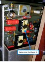
The A‐104 IC might be white as shown in the picture or it might be the typical black.
Rocking the IC
Almost invariably the problem is due to the fact that this IC is socketed and simply needs to be exercised in its socket. (I have yet to come across a defective IC.)
What I usually do is rock it back and forth a few times in its socket by pushing down on one end and then the other – you do not need to remove the IC. I do this several times and finally push in at its center to be sure the IC is fully seated.
Rarely have I had to re‐track the calibration tuning, and in making before and after comparison checks against a known FIM, the calibration accuracy has not been affected by doing this.
Back to Work
Once that is done you can check the Calibration Oscillator tracking.
- Tune the FIM to the low end of the dial.
- Put the FIM in the Calibrate mode.
- Peak the front panel “CAL OSC” tuning, and
- Slowly tune the receiver across the band, or bands, while at the same time adjusting the Calibration Oscillator Tuning.
Do not worry about absolute level at this time, but only that the “CAL OSC” tuning reasonably tracks the main receiver tuning control. As you tune you will probably see that at some points the calibration oscillator level indication will disappear from the receiver tuning, but it should only take a little bit of re‐adjustment of the “CAL OSC” tuning knob to bring it back.
Normally the pointer on the Calibration Oscillator tuning knob should remain somewhere between the 10 O’clock and 2 O’clock position over the full range of the instrument.
What I have described above does not take the place of a factory calibration, but it has resolved the described problems and in my experience it has not affected the accuracy of the instrument.
– – –
Burt Weiner, is the top gun at Burt I. Weiner Associates, a long-standing engineering firm in Los Angeles and its suburbs. Burt has not seen everything, but he is close.
Contact Burt at biwa@att.net