

Silicon Carbide Comes to AM Broadcasting Inside the BE AMX Transmitter

By Tim Hardy
Senior RF Engineer, Broadcast Electronics
[June 2026] Transmitters have come a long way. Tubes are gone, transmitters no long need huge rows of cabinets and many fit easily into a rack. Broadcast Electronics’ Tim Hardy is the designer behind the new transistors used in the new BE AMX line. Would you believe 5 kW in 5 rack spaces? Read on! (If you would like to see and hear Tim talk about the AMX, click here.)
A new AM transmitter family from Broadcast Electronics is introducing technology to the broadcast industry that, until now, has been the exclusive domain of electric vehicles and industrial power electronics.
The AMX series marks what appears to be the first use of silicon carbide (SiC) MOSFETs in an AM broadcast transmitter – and the implications for reliability, efficiency, and transient survivability are substantial.
WHY SILICON CARBIDE, AND WHY NOW
Silicon carbide power transistors have only been commercially available for a few years, and the devices used in the AMX represent an already-mature second generation of the technology.
Until recently, AM transmitter design was largely constrained by the power semiconductor ecosystem built around 400-Volt bus architectures – a legacy of universal power supply designs whose PFC stages standardized on that Voltage level.
The landscape has shifted dramatically. The electric vehicle market, with its 800-Volt traction systems, has become the dominant driver of power semiconductor innovation. The major semiconductor manufacturers are engineering their most advanced devices around 800-Volt-class bus voltages. The SiC MOSFETs in the AMX are rated at 1,200 Volts, operated from a 750-Volt supply – a 37% Voltage derating that provides substantial design margin. This is not simply chasing a trend; it means the AMX is designed around the same devices attracting the most aggressive development investment in the industry, which translates directly into better component availability, improved specifications, and a clear roadmap for further advancement.
Silicon carbide offers improvements across every axis that matters in high-power RF amplifier design, with no meaningful tradeoffs. Compared to conventional silicon devices at equivalent Voltage ratings, SiC MOSFETs provide higher power density, greater thermal efficiency, superior robustness under stress, and – critically for broadcast applications – dramatically better resistance to the failure mode known as secondary breakdown.
THE AMX AMPLIFIER: TESTED IN INDUSTRIAL RF
The AMX power amplifier module spent approximately three years in development, initially targeting both broadcast and industrial RF applications.
That industrial testing background is directly relevant: industrial RF environments expose amplifiers to widely varying and often extreme load impedances, providing a stress regime that broadcast-only testing rarely replicates. The result is a design that has been validated under conditions well beyond normal broadcast service.
The amplifier is a Voltage-mode class D H-bridge topology, which is standard for modern AM transmitters. What is not standard is the combination of the 1,200-Volt SiC transistors, the 750-Volt supply voltage, and the thermal design approach. Junction temperatures are maintained below 100°C even on hot days — a deliberately conservative operating point. The amplifier is rated for 5 kW continuous output, but has been operated at 15 kW in testing. The operating load impedance is 12.5 Ohms, matched to 50 Ohms through a balun transformer at the amplifier output.
Modulation is accomplished through a three-phase pulse-width modulator operating at 135 kHz. The polyphase architecture cancels fundamental switching frequency components, permits higher effective PWM frequencies for improved linearity, and reduces passive component sizes throughout the modulator stage. An FPGA handles PWM generation and RF drive synthesis, while an ARM processor manages system control, monitoring, and communications.
PER-TRANSISTOR PROTECTION: A NEW LAYER OF DEFENSE
Every transistor in the AMX amplifier is individually monitored by a dedicated protection circuit.
This circuit watches peak RF current in real time and will act to protect the transistor if current exceeds safe limits. A separate sensing function monitors the load impedance phase angle – because class D amplifiers operating in resonant mode require a slightly inductive load at all times. If the load impedance drifts outside the safe range, the transistors become heavily stressed, and this condition is sensed directly at the device level rather than inferred from reflected power at the output.
This per-device protection operates in a “hiccup” mode rather than a latching shutdown: it suppresses operation during the out-of-bounds condition and resets automatically when the condition clears. The result is an amplifier that can survive momentary load excursions that would destroy a conventionally protected design.
SURVIVING THE TRANSIENT THAT KILLS TRANSMITTERS
The single most technically distinctive feature of the AMX amplifier may be what the design team calls “safe mode” – a third operating state, beyond the normal positive and negative half-cycles, that is entered within approximately one microsecond of detecting a severe VSWR event.
To understand why this matters, it helps to understand exactly how high-VSWR conditions destroy transistors.
In resonant-mode class D amplifiers, the transistors must switch at a moment when the current through them is small and in the correct direction. This is what produces the efficient “zero-Voltage switching” operation that makes the design practical at megahertz frequencies. Under normal conditions, switching losses are negligible — the dominant loss mechanism is simple conduction loss through the transistor’s on-resistance. In a 1,200-Volt SiC device with 20 milliohms of on-resistance, this amounts to approximately 8 Watts of dissipation per transistor at 5 kW output – an almost astonishing figure.
The problem arises when a transient – from lightning, an antenna arc, or a sudden impedance step — disrupts the resonant condition. The load resonance frequency shifts, control of the current phase is lost, and switching begins to occur with large currents at the wrong phase. In the worst case, the current reverses direction, and when a transistor turns off with reverse current flowing through it, the body diode undergoes hard recovery. Hard recovery triggers a phenomenon called secondary breakdown: current concentrates in microscopic spots within the transistor’s drain rather than distributing uniformly across the device.
The resulting local thermal runaway can destroy a transistor in nanoseconds — faster than any conventional protection circuit can respond.
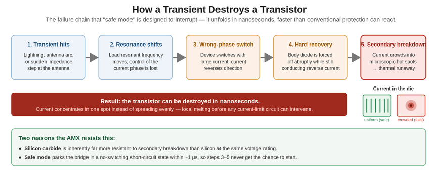
Figure 1. The transient-induced failure chain. A disturbance at the antenna shifts the load resonance, forcing the device to switch at the wrong phase; hard recovery of the body diode then triggers secondary breakdown, which can destroy a transistor in nanoseconds. Silicon carbide and the safe-mode state both work to interrupt this sequence.
Safe mode addresses this directly.
SAFE MODE
When triggered, the top two transistors of the H-bridge are turned off and the bottom two are turned on simultaneously, placing the load in a short-circuit state that allows current to circulate freely with minimal dissipation and no switching events.
The amplifier is effectively parked in a state where secondary breakdown cannot occur, regardless of what the antenna impedance is doing.
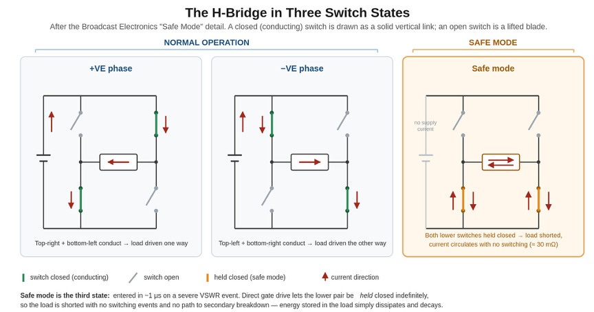
Figure 2. The H-bridge in its two normal half-cycles and in safe mode, following the Broadcast Electronics safe-mode detail. In safe mode the two lower switches are held closed and the two upper switches are open, shorting the load; current then circulates with no switching events and no path to secondary breakdown, and the amplifier presents a very low impedance (about 30 milliohms) to the load. Direct gate drive is what allows this state to be held indefinitely.
Critically, safe mode is enabled by a key architectural choice: the AMX uses direct gate drive rather than gate drive transformers.
USING DIRECT GATE DRIVE
Gate drive transformers, which are common in older designs, require continuous alternating drive to maintain transistor state – you simply cannot hold a transistor on indefinitely.
Direct gate drive allows the control system to hold the transistors in any state for as long as needed, making the safe mode state genuinely stable rather than a momentary condition.
The transmitter also enters safe mode whenever AC power is applied but the transmitter is in the off state – meaning the transistors are protected during standby, not just during operation.
Silicon carbide makes this protection significantly more effective. SiC transistors have substantially higher resistance to secondary breakdown than silicon devices to begin with. Combined with the safe mode architecture, the AMX design team projects a reduction in field failures attributable to transients on the order of ten times or greater compared to conventional silicon-based designs.
The next step is to ramp up the design to 750 Volts.
CREEPAGE, CLEARANCE, AND COMPONENT ENGINEERING
Moving from the 400-Volt bus Voltages common in older AM transmitters to 750 Volts demands rigorous attention to insulation coordination.
The AMX design follows UL standards for creepage and clearance distances. At 800 Volts, the minimum creepage distance in a pollution-degree-2 environment (realistic for a transmitter site) is 4 mm – double the 2 mm required at 400 Volts. In practice, the AMX PCB layouts achieve 6 mm or greater through techniques including milled slots in the board that force surface leakage paths to travel around the cutout rather than directly between conductors.
The transistor packages themselves have evolved to address this.
The modified TO-247 package used in the AMX includes a molded notch between the power leads, extending the surface creepage path to more than three times that of a standard TO-247. Decoupling capacitors on the 800-Volt bus are built as series arrays of 600-Volt-rated capacitors with Voltage-equalizing resistor networks, achieving ratings beyond 1,000 Volts.
As an additional mitigation: the three power supplies are connected in series to produce the 750-Volt bus, but that bus is referenced to ground at its midpoint through a resistive bias network. The result is that no point in the circuit is more than ±375 Volts from ground – the full 750-Volt differential exists only between specific pairs of conductors, not between any conductor and chassis ground.
But these circuits are not the whole story on protection. The harmonic filter provides another layer.
LIGHTNING IMMUNITY FROM THE FILTER
The AMX harmonic filter contributes to transient protection in a way that is easy to overlook.
Many AM transmitters use a simple low-pass output network with a minimal high-pass element, providing approximately 6 dB per octave of attenuation below the carrier frequency. The AMX uses a classical fourth-order bandpass filter design, which provides equal attenuation symmetrically above and below the passband.
At lightning frequencies – typically in the 10 kHz range – a fourth-order bandpass filter centered at an AM frequency provides more than 100 dB of attenuation. This means that even large lightning-induced Voltages at the antenna will be attenuated by a factor exceeding 100,000 before reaching the amplifier transistors. The bandpass filter also includes a notch at the third harmonic, which class D amplifiers generate in significant quantity due to their near-square-wave output waveform.
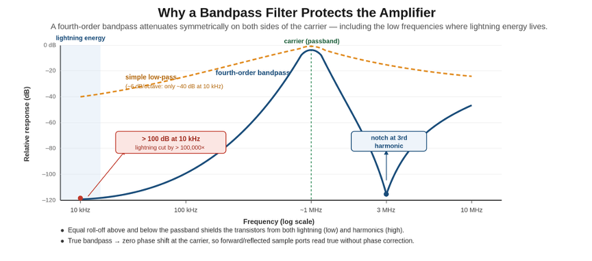
Figure 3. Response of the fourth-order bandpass output filter compared with a simple low-pass network. Because the bandpass rolls off symmetrically on both sides of the carrier, it delivers more than 100 dB of rejection at lightning frequencies and a notch at the third harmonic, where a low-pass network attenuates only weakly.
Because the filter is a true bandpass rather than a low-pass, it achieves zero phase shift at the carrier frequency – a property that simplifies the relationship between amplifier output and antenna current, and that also means the forward and reflected sample ports at the transmitter output accurately represent conditions at the amplifier without requiring phase correction.
THE POWER SUPPLY ARCHITECTURE
The AMX 5 kW unit houses three off-the-shelf 3,000-Wwatt switch-mode power supplies.
Each supply produces 250 Volts DC; the three are connected in series to generate the 750-Volt amplifier supply. The total installed capacity of 9 kW comfortably exceeds the maximum demand of approximately 7,500 Watts at peak modulation, with typical audio levels drawing under 6,000 Watts.
REDUNDANCY THROUGH SERIES CONNECTION
The series architecture provides built-in redundancy.
With one supply removed or failed, the bus drops to 500 Volts and the transmitter can continue operating at over 2 kW. With two supplies out, the remaining supply can still sustain over 500 Watts of output. Each supply also provides a 24-Volt output for auxiliary systems – because only one of these is needed to run control and fan systems, the auxiliary supply is triply redundant.
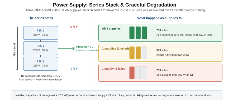
Figure 4. The series power-supply stack and its graceful degradation. Three 250 V supplies combine to form the 750 V bus with the midpoint referenced to ground, so no conductor sits more than plus or minus 375 V from chassis. Losing one or two supplies lowers the bus voltage but keeps the transmitter on the air.
The power output control follows the approach that has distinguished Broadcast Electronics AM transmitters for years: a variable power supply Voltage, controlled by the exciter, rather than relying solely on the PWM modulator depth. This approach preserves audio performance at reduced power levels, where purely modulator-based power control degrades linearity.
The supply output Voltage is adjusted identically across all three units simultaneously – a single control signal is distributed to all three, so they track together through the series stack.

EASY ACCESSIBILITY IN JUST FIVE RACK UNITS AND 65 POUNDS
The AMX 5 kW transmitter occupies five rack units and weighs 65 pounds – light enough to ship by courier without special freight arrangements.
The physical package reflects a systematic approach to serviceability: every component that might require field replacement is accessible from the front or rear of the rack-mounted unit without removing the chassis from the rack.
The three power supply modules and the power amplifier module are edge-card connected and secured by a single screw each; they slide out from the front after removing the front panel (two screws, one ribbon cable). The harmonic filter assembly is removable from the front after disconnecting rear connections. The exciter/modulator card and remote control board each remove from the rear with two screws. No side panels, top covers, or bottom covers need to be disturbed for any routine service operation.
The harmonic filter’s modular design has an operational benefit beyond serviceability: a broadcaster using the transmitter as a backup for multiple frequencies could maintain spare filter assemblies pre-tuned to different frequencies, enabling a rapid frequency change without a factory visit.
WHAT COMES NEXT
The AMX family is designed as a platform.
For example: the exciter chassis includes reserved space for an optional Orban audio processor, currently in development as an integrated option. Also, the FPGA-based exciter architecture supports dual AES digital audio inputs, with one intended to carry HD Radio MA3 all-digital baseband should the broadcaster wish to operate in that mode. And , the 10 MHz and 1 PPS synchronization inputs support frequency-locked operation, with phase synchronization of multiple transmitters a future possibility.
Some smaller variants of the AMX platform are planned, including a unit in the 1,500-Watt range using the same power amplifier module with a single power supply.
Higher-power versions are also on the roadmap; at those power levels, the design team indicates that iron-core transformers will likely return to the design – not as a step backward, but because at 50 kW, the economics and reliability of iron at 400-Volt secondary voltages are difficult to argue with.
Initial customer shipments for the new AMX series are anticipated to start in October 2026.
– – –
Tim Hardy is a Senior RF Engineer at Broadcast Electronics with more than 30 years of experience in AM and FM transmitter design, including the NA, XL, XR, and NX series at Nautel prior to joining BE.
– – –
Would you like to know when more articles like this are published? It will take only 30 seconds to
click here and add your name to our secure one-time-a-week Newsletter list.
Your address is never given out to anyone.