

Salvaged Parts Make A Useful Current Sampler

[January 2014] Most engineers have a “parts box” where various items gather over time, to eventually end up being “just what is needed” for something. Stephen Rutherford’s parts box came to the rescue.
I am a “Scrounger.” It is a trait that I picked up while serving in the U.S. Navy as an Electronics Technician. And I am absolutely sure many of my broadcast engineering brethren share this same trait with me.
The Gleaning Process
As this story starts, I was servicing several high-power FM transmitters at a co-located TV site.
While working on the rigs, one of the TV engineers asked if I could help them pull out a retired TV transmitter and help pull in the replacement. I was glad to lend a hand.
When the job was done, I asked the Chief what they were planning to do with the old rig. The bottom line was: nothing. So, naturally I asked if it was OK to pull any parts I thought I could use for project work. I was given a green light!
While culling a few pushbutton switches, low-level power supply modules and analog meter movements, I came across some small modules with high voltage wires running through them, pulled them out, and stuck them in my box of “stuff.”
Weeks later, I retrieved them and went on line to find out what they were.
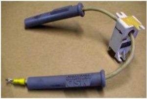
The “modules” are manufactured by F.W. Bell and the model number is the IHA-25.
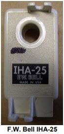 It is a Hall effect AC and DC current sensor, and that perked my attention.
The module will output a representative response to the AC and/or DC current present on the sampled conductor.
The specifications indicate 40 mV/Amp AC and/ or DC with a bandwidth of 50 kHz.
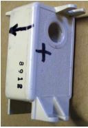 When I tested the first prototype unit, I found that the direction of the DC current into the sensor made a little difference in the sample output, so I marked the current flow arrow and polarity with a felt tip pen on the modules.
When connected with the flow in the right direction, the output was more accurate.
Power Supply
I cobbled a +/-15 VDC supply and a BNC connector to the output of the module.
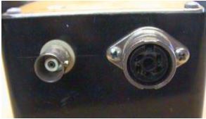
Sample and power supply Connections
The power supply I used is a Sola linear brick unit. Simply wire the AC mains to the input and wire the plus and minus outputs to the load. It is only rated for 100 mA DC output, but that is more than sufficient for this application.
The AC mains DIN input incorporates an EMI and RFI filter as a part of the connector. It is a redeployed component from a salvaged device.
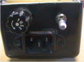
The toggle switch is a locking device – you have to pull out on the bat handle then move the switch into the ON position, same action to turn off the AC mains.
The DIN and BNC connectors also were in my junk box. Because the power unit container is non-conductive, I could have used a standard metallic BNC but I like using isolated ground BNC connectors. (I also like to use them with Switchcraft XLR connectors to make XLR to BNC converters for my audio test gear. I have made lots of them and have given a few away as gifts to other engineers.)
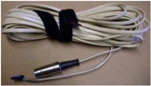
I used a four-wire telephone cord for the interface because it is flexible and flat, making it easier to slip under a rear door after setting the sensor into position.
Putting the Sampler to Use
The sample unit was now complete and I could take it along to my next FM transmitter assignment.
When using the unit in the field, I was originally concerned about the cable being unshielded. However, thus far, I have not had any problems with interference.
When the repairs were completed, I inserted the module into the high voltage line leading into the PA compartment of the FM transmitter I was working on.
The HV sample tap leads go through the IHA-25
After connecting my oscilloscope to the sensor I was very pleased with the display.
The indicated plate current was 3.0 Amps and the scope display was showing 2.4 cm deflection at 50 mV/centimeter sensitivity, or 3.0 Amps DC current.
Switching the scope to AC coupling and increasing the input sensitivity, the scope display appeared to be an audio signal. Slowing the scan rate to indicate more of a “fuzzy bar” type display and making small changes to the output tuning and loading controls, I could see the AC component of the plate current rise and fall in concert with the adjustments.
I compared the scope display changes with the RDL AMC-2 and I could see a correlation between the two. But, with a null display established on the AMC-2, an AC current component was still evident on my scope, although it was very small, about 6 to 8 mA AC. Still, the null sensed with the IHA-25 did not correlate fully with the AMC-2 null.
When I have the next opportunity, I would like to see what the AC current sample spectra looks like when “tweaking” the transmitter for minimum AM synchronous Signal to Noise.
I already can think of several applications for remote current sensing for which this product would be very well suited, especially when coupled with an Op-Amp circuit.
Any more ideas out there? What could you develop with this unit in hand? Let me know.
– – –
Stephen Rutherford is a contract engineer based in Lincoln, NE. You can contact him at: twicethefirst@gmail.com