

Limiting Static Voltage on Vertical AM Radiators
[February 2011] Few things are as much of a “welcome mat” for lightning as broadcast towers. Some of them stick the invitation as high as 2063 feet in to the air and, when the storms roll in, the engineers just take a breath and wait for it. Still, there are ways to reduce the number and severity of the hits. In this article, Phil Alexander focuses on AM towers and what can be done to protect the facility.
Since the first use of elevated antennas we have recognized the hazard of lightning strikes and tried to avoid them. Of course, once we recognized the value of series excitation of vertical radiators with their insulated bases and deployed more and more of them, the problem became clearly pronounced.
While dissipation devices may reduce the number of strikes preventing some of them, some lightning strikes have a current large enough to overwhelm any protective device known to man. The only safe strategy is assuming that no amount of dissipation will prevent a massive strike in all cases. Thus, mitigation is essential because sooner or later any vertical radiator will conduct a massive strike.
Defense
One common misconception equates lightning with a huge flow of direct current. A lightning strike is a dampening, alternating current, generally oscillating between ground and cloud at a rate in the LF and VLF radio frequency spectrum with harmonics well into the MF range. The result is that good transmitting antennas are inherently good lightning receiving antennas.
To fully understand our task of lightning strike mitigation we must confront and understand the implications of this fact.
No amount of DC grounding will prevent damaging strikes on an efficient AM transmitting antenna. If it did we all would be using ground- 2 ed, shunt excited radiators. The need for static discharge devices on shunt-excited antennas is sometime overlooked with very serious consequences.
Defense
At tower bases, static ball gaps are the first line of defense, and perform two valuable functions.
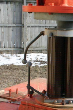
First, they limit the static charge build up on the tower by furnishing an easily ionized path for accumulated static discharge, thus preventing strike potential buildup in most cases. Second, they tend to bypass most of the lightning current flow directly to ground at the tower base reducing the risk that a lightning strike will overwhelm other mitigation and protective devices in the transmitting plant.
Ninety years ago Frank William Peek determined a spherical shape had the most repeatable arcing characteristics. Thus a ball gap could be set reliably as a static discharge lightning arrester, and the tower base static ball gap was born based on Peek’s formulas. At the time it was thought a gap between two balls would be relatively insensitive to humidity although modern research has shown a significant humidity effect.
The Right Distance
Correctly set, the ball gap spacing is adjusted for arcing in humid air at a voltage just above the maximum voltage that will be developed by transmitter operation – with positive modulation exceeding the FCC 125% modulation limit to accommodate brief overshoots that are not prevented by normal audio processing techniques. Thus, the aim is arcing at the lowest possible voltage that will never be achieved during a station’s normal operation.
One of the most common errors with ball gaps is setting them too far apart, making them far less effective, especially on low power installlations.
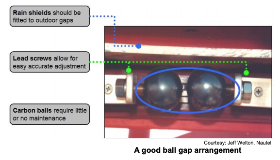
Another important factor is the correct placement of the balls forming the gap. Both balls should be located in the same horizontal plane so that liquids or semi-solids do not drip across the gap, thus shorting the tower base to ground.
Just as you might imagine, modern, low voltage, solid state transmitters are more sensitive to static charges, thus additional equipment such as that made by Polyphaser Corporation and other similar static mitigation equipment may be necessary for optimal protection. However, correct adjustment of spark gaps is the beginning of AM station lightning protection.
As a static charge builds on the tower producing a voltage above the maximum operating potential, a static arc ionizes the gasses in the ball gap briefly acting as a very low resistance, discharging the accumulated static charge of the tower. Minimum spacing of the static ball gap at the tower base and secondary gaps at other locations limits the potential in the rare event of a direct lightning strike on the tower.
Again, the objective is getting the gap as small as possible yet wide enough that any arc that occurs will self-extinguish once the tower’s static charge has drained away.
How Wide Should it Be?
There are many ideas about how to set the spark gap width. They range from the “credit card method,” which may work on some average one kilowatt installations with quarter-wave towers to “hit it with a hammer until it arcs and knock it open with one hammer hit in the opposite direction” (by the way, this is not recommended!), to actually calculating the voltages and resistances encountered at the tower base.
A spreadsheet, courtesy of Nautel Corporation, allows calculation of the maximum transmission voltage at the tower base and the arcing voltage of a gap setting depending on the influencing physical properties. You can download the spreadsheet here
One caution: While the positive modulation limit established in the FCC Rules is 125%, instant peaks may often exceed this value for very brief intervals in normal operation as a result of processsor overshoot. Thus is it wise to assume a positive peak of 140% or 150% and allow a safety factor for preventing arcs during normal operation. This is especially true with talk program operations where sharper, more energetic peaks may be more common.
– – –
Phil Alexander CSRE, AMD, is a veteran broadcast engineer based in Indianapolis, IN. Contact Phil at dynotherm@earthlink.net