

Growing Tower Farms in M/SP Part 4 – Finishing Touches and On the Air!

[November 2015] We bring our look at the Minneapolis-St. Paul Telefarm and Shoreview sites to a conclusion as Steve Brown shares the rest of the story of how these sites developed.
It was Winter 1991 and, it being pretty cold up here, most all outdoor work on the site came to a stop.
Because of the seasonal delay, we decided to fire up the plant into dummy loads to facilitate the adjustment and testing of the combiner modules. Unfortunately, the construction of the site was at a point where we had no large dummy loads and no source of water of sufficient quantity to cool them. However, some excellent solutions developed.
Two Steps Ahead, One Step Back
The first issue was handled by Bird Electronics, which supplied two water-cooled 80kW dummy loads with 9-inch Marmon flanged connectors to fit the patch panel.
We then contracted a well-drilling company to upsize the water well and pump (which was originally designed to supply just enough water for toilet flushing) to deliver lots of water to the dummy loads. For protection of the loads we also needed to add water flow metering to the transmitter interlock circuits.
Of course, you can probably guess what happened next. One night that winter, a station at the site clip-leaded around the protection circuits to test a transmitter – but forgot to turn on the water valves for the dummy loads. Yep. Without water running, both loads were toasted in a very short period of time.
Combiner Setup
After the dummy loads were repaired, the technician from Britain that Alan Dick sent to tune up the combiner wound up spending most of the winter getting things adjusted.
Unfortunately, what we found was the combiner parameter measurements taken when the system of the s cold would drift as real transmitter power was applied to the modules.
![]()
Part of this was problem due to our specification that the combiner system have very good phase response across each station pass-band (group delay) as well as amplitude response. We also required that station-to-station isolation through the system did not rely on any turnaround loss in the transmitters, since no transmitter manufacturer had specified that parameter at that point.
Disagreement
At this point, a disagreement between consultant Dean Sargent and the Alan Dick folks put us in a quandary.
The bullets in the 9-inch rigid line showed some arcing marks after we had tested the system into the dummy loads for several hundred hours of operation. Sargent became convinced that there was no way the line they had fabricated would handle the combined 150 some kilowatts of energy over the long term.
Alan Dick’s people determined that the issue concerned the “setting” of the bullets, springing them out a bit to increase their tension with the inside of the inner conductor. Sargent balked at this idea and suggested that it was in our better interest to scrap the entire combiner and replace it with another vendor, who seemed to be working with him to make this happen.
Compromise
A compromise was finally reached to add temperature sensors to various points on the outer surface of the 9-inch line and tie those readings back into the monitor/protection system so that if the line did overheat the system would shut down before damage was caused.
We pointed out that, because of the surface area of the outside of 9-inch line, the damage to the bullets and center conductor would likely happen well before the temperature on the outside got anywhere near dangerous, but that argument did not wash well with Sargent.
In retrospect, the bullets never have been a problem since they were adjusted, but the fragile wiring and the analog to digital converters that were added to monitor the temperatures have occasionally flaked out and caused half power commands to be issued by the system.
After this little dustup Sargent resigned from the project.
An Unexpectedly Large Bill
About this time, a humongous power bill from the utility company hit the bookkeeper’s desk.
This seemed a bit odd for a building that should have been using very little power since the only things operating were a few fluorescent lights and perhaps a soldering iron or two.
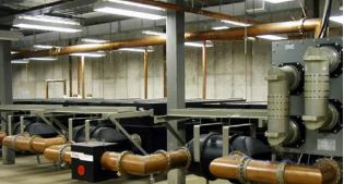
In our design, the building main power distribution was specified to be 480 Volts, three phase. The air handling and cooling were also designed to operate at 480 Volts for efficiency. Each transmitter room was fed from a separate main panel disconnect at 480 Volts, but each room also had a step down transformer to provide 110/208 Volt WYE connected three phase to accommodate the transmitters, rack power and outlets.
However, at the time there were no transmitters operating and little other equipment installed.
Discovering the Power Factor
It was at this point that the term “Power Factor” entered our vocabulary.
In our anticipation to be ready to transmit we had left all the fused disconnects in the 480 Volt main power distribution panel switched “on.” Without little or no load on the outputs of the step down transformers the power factor nose-dived.
To explain: Power Factor is a measure of real AC power consumed as compared with the reactive AC power needed. It is similar to matching a transmitter to an antenna; the transmitter is most happy delivering RF power into a pure resistance, like 50 j0 ohms for example. Add reactance to the antenna – the transmitter quickly becomes unhappy and will probably shut itself down. Think of an FM antenna in winter with a thick coating of ice.
Similarly, if equipment connected to a power line is purely resistive, like a space heater or a toaster, then the power factor calculation (being all resistance versus no reactance) is 1.00 and the power company is happy. If the load is reactive – it has capacitance or inductance in addition to resistance – then the power factor becomes less than 1.00 and the power company becomes unhappy.
Unlike a transmitter which will just shut down to protect itself, the power grid will simply keep supplying more power.
In the Power Co. Penalty Box
Ordinary power company billing meters just measure the resistive power portion. This is a problem for the power company, as they may not realize they are supplying more instantaneous power to overcome the load reactance component plus the resistive component.
However, in our case the power company had installed a Power Factor Meter along with the standard power billing meter as they had anticipated there being reactive loads due to all of the motors in the air handling and cooling systems. Long story short, the unloaded transformers in each room looked like a big inductive reactance and a horrible power factor to the power company which, being unhappy, billed us accordingly for the reactive power.
Although the actual used power bill was quite low, the penalty levied due to the accompanying 0.31 power factor was insane.
Since then it has been a site mandate that the 480 Volt disconnects be left off unless testing or actual operation is in progress. Since then, no similar power factor electric penalty has ever been applied to the site. With all the transmitters and air handlers operating normally the power factor is comfortably above 0.90.
Back Outside to Finish Up
Eventually Spring 1992 arrived, and the tower reinforcement finally got finished, and the “big iron crew” started threading 20-foot sections of 6-inch EIA flanged transmission line into the tower.
I must say that they did a remarkable job of this part of the project, considering that there were already six other large lines serving television antennas on the tower. They also left the spud wrenches on the ground when they snaked 72 7/8” Heliax feeders to the dipoles from the tower-mounted power dividers and made a neat job of it.
The only issue came up early on, after a small amount of our line had been hung. Our site manager George Werl rode the elevator up to where the crew had stopped for the day and noted that none of the bolts on the line had lock washers installed under the nuts. “You wanted lock washers on those?” the tower crew chief asked George the next day.
We had hired George for his powers of observation and based on the fact that he could be (and still is) an equal opportunity nitpicker when need be, he assured that crew chief that lock washers were expected.
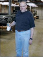
George Werl on site
Full System Testing
In August of 1992 it was time to test the system and get ready for operation. The first tests were to confirm that the whole system met our specifications for performance.
We decided to measure the response of the system under full power by driving the power amplifier bricks in each transmitter’s exciter with the Alan Dick supplied network analyzer and connected the receiver port of the analyzer to the directional coupler at the output of the combiner string.
Those present can attest to the fact that a Continental FM transmitter can maintain a reasonably flat power output level without folding back due to VSWR if the sweep across several FM channels happens quickly enough, and the test sure sounds interesting on an FM receiver tuned in when testing late at night. It was truly a use of the old FCC term “experimental period” when we did those sweeps.
The intermodulation measurements for each potential product took the most time, but the combiner isolation and whatever turnaround loss the transmitters gave us produced excellent results. No 3rd Order product exceeded -90dBc – some 10 dB better than the legal limit – and many of the product levels were below the capability of the measuring equipment.
Shortly after the tests were completed the proper papers were filed with the FCC, program test authority was granted and we were really on the air, just some 13 years after “The IDS stations” began their testing in downtown Minneapolis.
Mostly Trouble-Free
Since those days there have been a few problems with the system, none major, and most involving nitrogen gas loss in all those coax connections.
Additions: In 1997 station #9, then WXPT-FM, 104.1 MHz was added to the combiner string. And, as we had preplanned for emergency power, during 2006 a 1 Megawatt generator with lots of fuel capacity and transfer switches was added to the site.
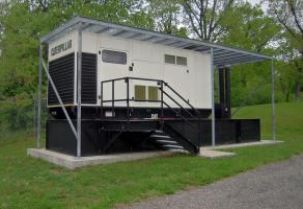
The 1 Megawatt generator, ready for action
HD radio operations began at about the same time, and the “overkill” of air handling and AC power capacity paid off, although one air handler can no longer handle the heat load by itself on a scorching day.
Before the HD project began for each station George Werl realized that Allan Dick had brought the reject feedline back down the tower from the power splitter hybrids. He thought that might make possible to “inject” HD radio signals into those lines, rather than using high level combining.
Unfortunately, this idea did not pan out because the original 7/8-inch Heliax lines running to the tower-mounted hybrids would have needed to be upsized, triggering a tower rent increase from the landlord –and possibly even structural modifications to the tower itself.
Collaboration Reigns
This project was not all just work for us local engineers. Many friendships were made over the decade of work. During construction and testing we usually had a weekly meeting at the site, which continued long after construction ended. It became known as “Heineken Friday.”
Sometimes the ideas tossed around could get quite interesting. For example, about that time there was an abundance of new audio processors flooding the market. I had been in a bull session in the mid-1980s with Mark Durenberger, Bob Orban and Bill Sacks discussing was Eric Small’s new CP-803 composite processor.
Although some were dismissive of the idea of composite clipping, Bill Sacks jumped on the “idea” of using a couple of LED’s tied back-to-back across the composite line as a simple clipper, and he named it “The Klippopotamus; the hipper clipper for that round sound.”
Intrigued by Bill’s imagination, we decided to go a giant step beyond the diodes and create a passive audio clipper that worked in the RF domain. We set the “Klippo” up to process all of the stations by clamping it to a section of 9-inch rigid transmission line, supposedly making the playing field really even for all stations.
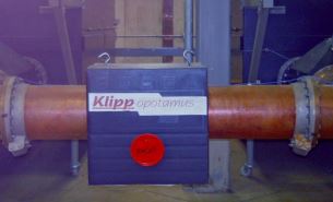
The World Famous Kippopotamus on guard
The Klippo is still on site after all these years, “guarding” something.
We even made a video vaguely describing how to construct and install a “kit” version of the Klippo, followed with a testimonial from a pseudo-famous radio programming consultant praising the device after activation at his stations. If you are interested in our “bleeding edge technology” from 1992, you can check it out here.
Well-Built = Solid Operation
It is with some pride that we can say, almost 24 years later, things are still humming along at the Shoreview FM Group Master Antenna plant.
Changes? Of course. Lots of them. All of the original Continental transmitters have since been replaced, as has the original BE rig. HD transmitters are in place now. Stations began using T-1 service as the primary STL’s. With Alan Dick out of the high-power broadcast business, a few minor antenna parts have been provided by Electronics Research. And the 20-year guarantee on the roof ran out just about 20 years after installation, the roof began leaking on schedule, and was replaced.
The monitor protection system is way obsolete, but still does its job – the stability of the system is clear from the parameter monitor.
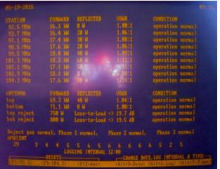
23.5 years after installation the monitor still works!
If you come out to visit the site, you may notice a special room: the 10th transmitter room was never occupied, so it has been turned into the junk room everyone always dreamed of having, full of old transmission line, STL antennas, reel to reel tape dinosaurs, and a variety of components left over from various upgrades and the HD radio additions.
Meanwhile, some upgrades to the first tower over at the Telefarm were completed in 2000. It now rises 437.7 meters (1436 ft) from the ground (its geo coordinates are 45°03′44.0″N 93°08′22.0″W). Similar work on the second tower, which rises 438.3 m (1438 ft), was finished in 2001. Most FM stayed at Shoreview.
I have been retired from “my” station (WLTE-FM) for over ten years now. But once in while I still wander on out to the site (they let me keep a key – and it still opens all the doors!) and marvel at the combined brain power, cooperation and financial wherewithal that let this project happen.
– – –
Steve Brown, aka the Radio Ranger, is now retired from WCCO-FM and enjoys backpacking in the Land of 10,000 Lakes.
He agreed to share his memories of how the FM stations in Minneapolis-St. Paul learned to improve their facilities and maximize coverage. You can email Steve at:
radioranger@comcast.net