

The Folded Unipole

 [August 2015] Over the years, Ron Nott has helped many stations solve transmission issues. Sometimes, he finds the unipole to be the right solution – even for a directional antenna.
AM broadcasters have been using the folded unipole now for well over than five decades, providing a good track record as to its efficacy. For some installations it can make an otherwise unstable system viable.
A Proven Design
Possibly the first time the design appeared in print was a 1952 article in Radio Antenna Engineering by E. A. Laport.
Over the years, there has been little change in the fundamental technology, but its use has led to a number of improvements, as well as identifying some of the unipole’s weaknesses.
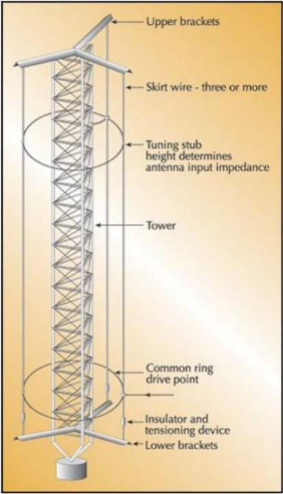
A unipole uses mounts at the top and bottom of a tower to hold fixtures where wires are attached that parallel the tower, in effect, by “folding” the antenna in on itself.
Additional connections also are made for the feed and tuning/matching points.
The result is that, electronically, the tower width is enhanced; a folded unipole on a short tower normally transforms a low drive point resistance upward, which can improve efficiency and provide easier impedance matching.
Another advantage of the folded unipole is that it is installed on a grounded tower. This eliminates lighting chokes and provides a more direct path to ground for lightning.
In a three-tower
directional
The unipole approach even performs quite well in directional-antenna service if it is properly incorporated into the design.
Furthermore, when a unipole is installed in an area prone to flooding, it can be designed to continue functioning when series-fed antennas fail. Using folded unipoles In a three-tower directional Still another advantage of the grounded structure is that it also allows the installation of UHF and VHF antennas for rental income on the tower.
Not for Everyone
In general, while retrofitting a thin, series-fed tower will result in some improvement.
At the same time, just installing a folded unipole does not guarantee the broader bandwidth one might expect from a wider tower face, especially in the case of an antenna significantly shorter than a quarter wave.
Higher Gain?
Years ago, it was thought that a unipole provided increased antenna gain and more circular polarization. Neither of these outcomes is true.
In some cases, the folded unipole may provide a small gain, perhaps a fraction of 1 dB, because of the decrease in the length-to-diameter ratio. This causes a slight reduction in the velocity of propagation within the antenna, which may make the tower appear to be slightly taller than it actually is.
However, in any case, there is no dramatic improvement.
On the other hand, where the bandwidth has been improved, there also have been apparent improvements in the effective range of the station due to improved sideband VSWR.
Putting Up a Unipole
If top loading can be incorporated on a short tower, the unipole can be designed to provide support brackets for the top loading as well as the skirt wires.
The first thing to remember is that there is more involved in using unipoles than just suspending some wires alongside a tower. For example, if the skirt wires are placed too close to the tower, the shunt capacity between them actually can defeat any advantages.
Early unipoles often were built using guy wire in the skirts, but the steel wire would cause a 20 percent or more loss in efficiency. For better efficiency, the skirt wire must be copper or aluminum clad. The wire should also be stranded to prevent wind vortexing, which causes vibrations that could ultimately destroy the antenna.
As a Rule of Thumb, in order for the unipole to achieve decent operating characteristics, it is important to mount the wires at least 18 inches from the tower face – and preferably 30 inches – except in special cases.
Model IT Before Construction
The folded unipole can be modeled using NEC programs, but this can be time consuming.
The late John Mullaney had a program written specifically for designing this type of antenna that was fast and usually accurate. Using the program the engineer can change parameters to achieve the desired results.
Some points to note:
- As noted, the impedance of short towers may be transformed upward. When a short tower is retrofitted with a folded unipole, an inductor may also be placed across the base insulator in order to increase the drive-point resistance. In some cases this even can improve the antenna efficiency. However, it must be pointed out that for high transmitter powers, short antennas may find rather high RF currents through the inductor.
- Bandwidth may be optimized. While other factors are also involved, an antenna height between 105 and 115 electrical degrees may be found to have extremely broad bandwidth. This has been confirmed in practice.
- In some instances, using a unipole can allow an FM or communications tower to serve as its supporting structure. If the structure is too tall, the upper portion can be detuned, but bear in mind that if one tries to do this, the guy wires must be segmented, which may be the most expensive part.
– – –
Ron Nott, K5YNR, is the founder of Nott, Ltd in Farmington, NM. With a background in broadcast, electrical generation, and manufacturing, Nott has developed many solutions for broadcasters.
His email address is ron@advantas.net