

FM Antenna Systems Maintenance: Preventing Signs of Impending End of Life Part 2
[November 2018] We continue with Tom Silliman’s discussion on the things that can cause problems with FM antennas, and how proper maintenance can prevent those problems. Who better than the manufacturer to help up keep the transmission system going at full speed? Here Tom tells you what to do and why.
What is involved in the maintenance – the care and feeding of a key part of your transmission system – the antenna?
True, the most important part of the system is far above your head. But today there are more ways to “see” what is going on, in addition to VSWR readings and tower crews. Climbers can not only inspect the antenna but can take pictures (or even send videos to the base). And drones can now be utilized quickly and safely to show what is going on up there.
As we discussed in Part 1, having a plan for routine inspections and prompt maintenance repairs will give your antenna and the transmission system a long, stable life.
Dealing with High Wind Effects
There is a large problem that can occur with legmounted antennas occurs when the antenna is exposed to high winds.
Such wind force can cause the antenna to rotate around the tower leg if the force of the wind on the antenna exceeds the reverse moment the bracket u-bolts produce.
To eliminate this potential problem, at ERI, we add an anti-rotation bracket to our leg-mounted antennas. This bracket can be made of metal or fiberglass – connecting the antenna bracket to an adjacent tower leg. This bracket will then go into a tension or compression mode during high wind conditions to eliminate antenna rotation around the tower leg to which the antenna is mounted.
Face-mounted antennas are braced off of two legs so that your bracket can produce a significant reverse moment that eliminates antenna rotation around the tower. I designed our support bracket in 1975 to make it flexible so that the bracket could move in hundred mile-an-hour winds, allowing the entire antenna and bracket to move together.
Furthermore, our antenna brackets are made from stainless steel. This distributed the load between the steel bracket and the antenna harness. Since the deflection was linear, no damage would occur.
Vortex Shedding
When wind hits a cylindrical surface – typically a low velocity is the worst – there are different failure modes that can occur due to vortex shedding.
Constant wind blowing on a pole will alternately form vortices that break off from the pole – alternately on the left side and then the right side. This results in a vacuum on one side and high pressure on the other side, and your pole moves from side to side perpendicular to the direction of the wind.
This can cause premature failure of poles and if the antenna is way up on the pole it can be a problem for the antenna as well as the pole itself. It can be eliminated by adding material or vanes to break up the vortices. If there are side-mounted antennas on the pole, these antennas will normally break up vortex shedding.
Controlling Cortex Shedding
Going back to vortex shedding: you can absolutely predict vortex shedding if you know the diameter the cylindrical structure and there are no antennas or feed lines mounted on the structure.
By calculating the frequency of the movement, you can know every mode that will occur. The low frequency mode is usually the worst mode, but there are modes that occur at wind speeds up to 80 miles-an-hour.
The best solution is to add strakes to the pole. Strakes are perpendicular vanes about four inches high that wrap over and over around a pole to catch the wind and break up the vortices produced by constant winds. This significantly reduces the movement caused by vortex shedding.
We have added strakes to poles many times, and it works well to eliminate pole movement in steady wind conditions. You can also add mechanical diameters such as a bucket of marbles – anything that will absorb the mechanical energy the vortex shedding produces will work.
Fix It or Lose It
Metal poles that are continually moving due to vortex shedding for a long time can fail due to fatigue.
I have seen this many times. Any mechanical system, has a number of times it can be flexed before it develops fatigue. This is predictable – and a big problem from vortex shedding on topmounted poles on towers.
paint that we use on melamine
A high-power panel antenna with a rubberized paint that we use on melamine
On the antenna shown, when we realized the surface of the fiberglass was starting to deteriorate, we painted all the insulators. That was three years ago, and you can see these insulators continue to be in excellent condition.
This is one more example of how periodic maintenance extends the lifetime of antennas. Your support towers should also be inspected, and we recommend such a tower inspection every five years. Guy wire tensions should be checked as well, and if necessary, the wires should be adjusted to proper tension.
Galloping Guy Wires
One of the biggest dangers to your antenna occurs when the guy wires start to “gallop.”
This occurs primarily with tall towers over a thousand feet. When winds blow from a certain direction while ice is forming on the wires, the ice takes on a form like a wing and, at a certain point, the wire starts “flutter” or gallop up and down, violently shaking the tower.
In addition to damaging the tower, galloping guy wires can cause cracks in the antenna components and actually limit the useable life time of the antenna
Snubbing the Flapping
Galloping wires can be avoided by introducing snubbers. If your own towers over a thousand feet, you really should consider this product.
 The snubber has rigid anchors on either side of the wire and has wires attached to shock absorbers that go up to the wire where a pully is installed on the wire.
The pulley can ride up and down the wire tied to the shock absorbers. Then if the wires try to gallop, the snubber wheel subdues the movement and the shock absorber absorbs the energy. In the end, the tower it is much more stable.
I strongly recommend this for areas with wind and ice or if your tower is over a thousand feet tall. It will increase the life of your tower and all the appurtenances.
Proper Design is Important
Another example relating to tower movement happened in Minneapolis where a Magnum Tower was originally designed, but the tower designer left icing effects out of the wire calculations.
When this error was found, the tower was reinforced. However, the antenna that was mounted on that tower kept failing it would fail every couple of years.
We did an analysis of the tower using a finite element tower design program and found that, after it was reinforced by a third party to cover the fact that it did not have ice calculations on the original wire design, they still left off the reinforcement where the antenna aperture was.
We added reinforcement to that aperture, and since that time, the antenna has worked without issues. So again, tower movement is a big deal.
Correct Guy Wire Tension
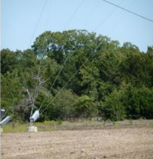
Another problem situation is where guy wires have not been inspected, and end up without sufficient tensioning.
One low tension situation was in Knoxville, where the original design was wrong. Everything mounted on that tower kept moving too much. The movement finally ended when we properly tensioned the tower.
Another bad outcome was in Austin, where the antenna cracked because a tower crew had been working on the tower and left the tower guy tensions too low when they were finished working on the tower.
As I said, I recommend that, if you are on a any kind of guyed tower, you check the guy tensions of the guy wires at least every five years – if not every three. As we just noted regarding tall towers, if those wires are under-tensioned and you do not have snubbers, there is no question but that you are going to get excessive tower movement and eventual system failure.
Sidemounting Issues
Pictured here is a side-mounted antenna:
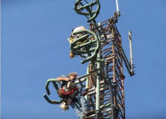
inspecting and replacing insulators
An ERI crew at work inspecting and replacing insulators
This was an example of where we reported that insulators were starting to deteriorate due to solar exposure after 25 years. When we climbed the tower, we could see where the insulators were leaking and where the resin had deteriorated due to exposure to the sun. The outer layer of fiberglass was loose without the fiber glass resin.
We removed the worn out insulators, replacing them with new insulators manufactured with plastic rather than with fiberglass.
Seacoast Installations
After solar exposure, among the more corrosive things in the natural environment is salt water. Yes, we are talking about coastal stations.
For example, at seacoast broadcast tower installations on the east coast of Florida, salt air forms a salt fog that moves in on towers. The fog bank might hit the site at as high as 700 feet above ground and can result in accelerated tower metal degradation.
Towers that are near to a sea coast should be inspected every five years.
 The inspection should include inspecting the guy wires for wire deterioration and the tower legs for leg steel deterioration. Unfortunately, most FM Broadcast tower owners do not schedule such periodic tower and antenna inspections.
Salty Air is Not Your Friend
One tower I inspected was in perfect condition for the first 600 feet – but at about 700 feet it had holes in the tower legs that you could put your fist through. That signified the end of life for that whole site.
The original plan was to take the tower down using a 200-foot gin pole. This plan was later modified. We used a helicopter to remove most of the top mounted pole on that tower, and this reduced the required gin pole height significantly.
By the way, the original tower had hollow legs. The tower was replaced with a new tower that had solid leg steel.
Salt Water Remediation
If salt gets on the insulators it can cause a premature failure.
Insulator damage can be prevented by adding radomes to the antenna. Guy wires can also deteriorate, as shown.
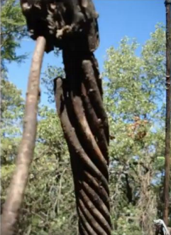
Here is an example of a tower leg in Florida where salt air has resulted in a guy wire failure. We repaired this after an inspection discovered the problem.
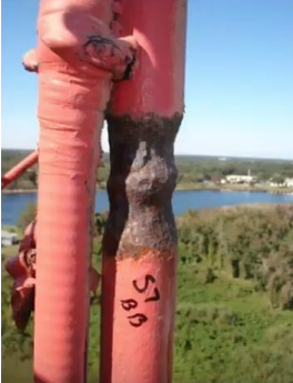 Another example of salt air causing tower deterioration is shown here. Here, a tower leg was rusting where the metal clamps were installed to hold a cable to the tower let.
It is a tower leg necking that actually can be repaired, but you have got to put on external clamping that probably should be welded.
Lightning Damage
The nice thing about lightning damage is that it does not really affect the long-term lifetime of your antenna.
I have seen lightning hit the individual bays of a side-mounted antenna. This can result in damaged insulators, damaged radomes, damaged antenna radiating elements, and damaged interbay rigid coax.
All of this damage can be repaired. It just requires maintenance. It does not mean the end of life for the antenna, but it can be a difficult problem to solve.
The typical symptom of a lightning hit is a system VSWR transmitter trip. Normally, you just turn the transmitter back on, and if there are no air leaks, everything works normally.
Inspect from Base to Top
On one system that we inspect on an annual basis, a nine station FM Master Antenna suffered a single VSWR trip prior to our next inspection.
The system had been brought back up to its full power, and it worked fine. But when we inspected it later that year, we noticed what looked like arc pits on the cover of the open end of the antenna’s insulator. When we opened up the antenna by removing the insulator cover, we found that the plate had taken a lightning hit.
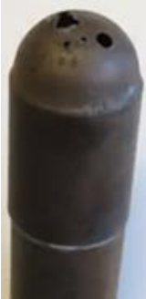
The strike tracked the inside of the insulator and went to ground. This was what caused that trip earlier that year. We cleaned up the inside of the insulator, replaced this radiating element, put it all back together, and it has worked fine ever since that inspection.
Radome Failures
If an antenna element inside a radome goes into corona, a plume of fire will rise from the surface of the metal element.
A plume of fire will continue as long as the FM energy fed into the antenna supports the corona arc. This can cause a radome to melts and, typi- 6 ically, implode onto the antenna element that the radome encloses. This usually happens when antennas are located at a high altitude with relatively thin radiating elements.
On the other hand, when a lightning strike hits the radome itself, the pressure inside the radome rises very quickly resulting in the radome literally exploding due to the pressure rise.
I have seen this happen seven times. Usually, when you show up to see what happened, you find the parts of the exploded radome somewhere out on the tower site. Often, the antenna itself is fine. If the radome is not replaced, the antenna element without the radome will be exposed to ice in the next winter season. This will result in an increased VSWR and possible a VSWR transmitter trip.
That is when you will find the radome out there in the field, install a new radome on the antenna, and eliminate the ice problem. Of course, if you schedule regular inspections, you would find that missing radome before you have any issues with ice.
Loss of Air
FM broadcast antennas are virtually always pressurized with dry air or nitrogen.
The pressure keeps moisture from entering the antenna and feed line. Also, the higher pressure increases the rated Voltage breakdown of coax. If water does get into an antenna and settles on the Teflon insulators inside the antenna, arcing can and usually does occur.
Locating the place the air is lost often will point to the source of an antenna problem.
Listen Carefully
During one inspection of a tower in Minnesota, I was told that the antenna was not holding air pressure, but was not exhibiting a very high VSWR.
To find the leak, I had the station put 15 pounds of air on the antenna feed line, and I climbed the tower putting my ear to the coax to see where the air was going. Going up, I could hear the sound of the air traveling up to the antenna.
Finally, as I got all the way to the top, it seemed like there was no place where there was a leak.
The Last Place to Look
But then, as I was hooked off to top of the tower, I looked at the antenna and suddenly realized I could see the inner conductor inside the quarter-wave stub that was on top of the array!
A perfect round hole the size of a quarter had been burned in the coaxial outer conductor by a lightning strike. Other than making this hole in the outer conductor, the lightning strike did not cause any damage to the coax quarter wave stub.
The fix came quickly: I got some tape out and started taping. Almost immediately as I started taping over the hole, I got a call on my radio, “You found the leak?”
Several climbers had been looking for this leak for a week, so they were surprised at my luck. In fairness, listening for the sound of the air in coax will lead a climber to the leak.
Antenna Inspections
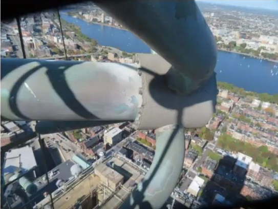
Large antenna systems like the FM antennas on the Empire State Building which I built in 1993, the Senior Road tower in Texas, and the antennas on the Prudential building in Boston are inspected on an annual basis.
The Prudential Building antenna has been on the air continuously since 1990. It has not really been trouble-free, so it gets inspected every year. Typically we will find things and fix them – buttons and hangers, for example. You will find broken hanger springs or pressure leaks from worn out insulators.
As I mentioned earlier (in Part 1), if you have a transmission line going through a high power FM aperture and one of the buttons comes out on one of the hangers, you can get metal-tometal contact. They can either be coated or replaced.
Unfortunately, again, at most sites antennas are only inspected when they have a problem.
Repair or Replace
Sometimes, the issue is whether to repair an antenna or replace it.
In Michigan: we had an antenna that was having problems. I told them to ship it in and we would rebuild it. We analyzed the tower – it was designed properly, but it lived right on the coast of Lake Michigan, with icing and wind.
We found the blocks were broken, the antennas were bent, and its welds were broken. Essentially, the antenna was producing too much load for that tower.
In our shop, we rebuilt the antenna and sent it back to the station. Surprisingly, the station owner got angry with me, calling me to say: “I could have bought a new antenna for that.” I replied, “You got a new antenna! We replaced almost every part in that antenna.”
Signs of End of Life
Here are some of the reasons that can be a cause of the end of life of your current antenna system, and require that antennas are replaced.
- New proven technology: if you have had an antenna for 15 years, and a new design comes out, or your major listening population has changed direction.
- A loss of pressure can indicate a major problem.(But as mentioned earlier, a loss of pressure might indicate a problem that can be corrected without replacing the antenna array.)
- Periodic VSWR trips that cannot be stopped, caused by, for example, corona during fog on the West Coast of the United States can only be corrected by antenna replacement.
- Finding antenna parts on the ground around the tower. I have seen this happen after massive ice storms on towers where ice shields were not installed above side mounted antennas. You will find that you have a massive air leak and a high standing wave.
- If, while inspecting the antenna and noticing there are many holes in the flex line feeding the antenna as well as holes in the antenna itself, it is probably time to replace that antenna system.
- Infrared or TDR testing of the coax shows high heat or power return at most of the bullet locations in the system.
- A larger building going up next door to the one in which your antenna is located. This resulted in the One Shell Plaza multiplex facility in Houston, Texas, to be replaced due to the shadowing and multipath caused by taller buildings in Houston. (That multiplex was replaced by the Senior Road Tower facility located south of Houston.)
The Real End of Life
My definition of end of life is simple: the end of life of an antenna occurs when the costs of repairing the antenna exceed the cost of replacing it.
If properly maintained, there is no reason that a side mounted ERI FM antenna should remain in service for less than 30 years assuming that none of the issues presented earlier exist.
Setting Up Maintenance
A good place to start is a discussion with the manufacturer of your tower and antenna.
Without doubt the manufacturer knows, from experience and field reports, what are the major problems that afflict your tower or antenna. Based on location, height, and the exact antenna, it is likely the manufacturer knows exactly what parts fail and sometimes when to expect them to fail.
Your periodic inspection plan should include inspection of the following:
- The tower structure – climbing inspection
- The foundation for the tower and guy anchors.
- The guy wires.
- The rigid line, coax, and the hangers – via a climbing inspection
- The antenna itself and its mounting hardware – via a climbing inspection.
- If the technology is available, visual inspection of the entire system using infrared detection – from the filters in the transmitter room to the radiating elements of the antenna array. This can be done using a drone while the system is on the air.
- Electrical measurements of return loss and distance to fault of the transmission line and the antenna array.
Setting up and following this plan will usually ensure many years of trouble-free service.
If you have any questions, please feel free to email or call me. We are happy to help.
– – –
Tom Silliman is the President of ERI Inc, in Chandler, IN. Tom is well-known for his work, whether designing and constructing towers or working on them and antennas at hundreds and hundreds of feet. You can contact Tom at: tom@eriinc.com