

Bad Axe Mixer: A Blast from the Past

[August 2021] At one time, it was common for broadcast engineers to build everything from consoles to transmitters and antennas. Lurking in many stations’ basements are some interesting relics. Michael found one and decided it would be an interesting project to restore it.
Younger broadcasters may not know the challenges they would have faced 60 years ago, when a remote broadcast took major engineering work to get on the air.
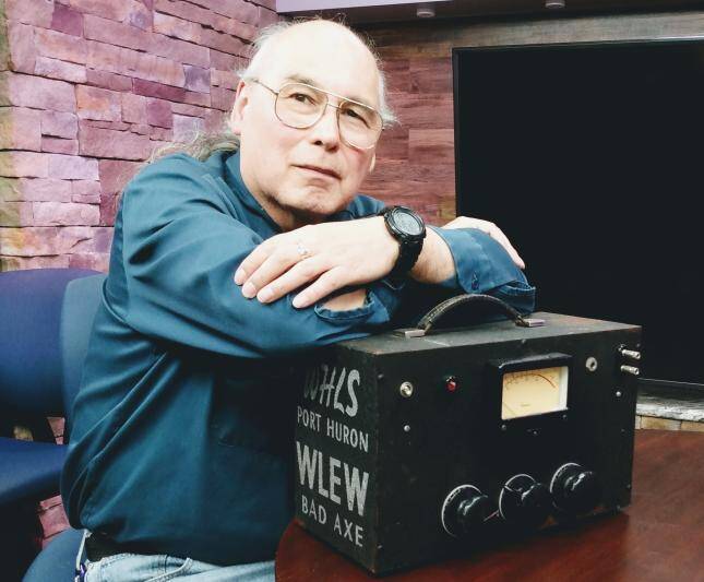
The “Bad Axe” mixer is a vintage homebrew microphone mixer that was built by someone at WHLS (Port Huron, Michigan) or WLEW (Bad Axe, Michigan), a pair of commonly-owned stations.
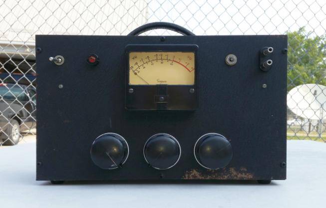
Front view of the Bad Axe mixer
The mixer had sat in the basement of a retired radio engineer for many years.
The parts used in it suggest it harkens back to circa 1953 and was undoubtedly used for numerous remote broadcasts, including local sports events in the Port Huron and Bad Axe area (in the ‘thumb’ of Michigan’s lower peninsula) between 1955 and 1968, when Marti VHF (and later UHF) transmitters units replaced telephone dial-up connections and became the “go-to” for remote broadcasts.
AN INTERESTING LOOK BACK
There were no labels on the mixer, but its operation is so simple, they are not really needed.
The two left-hand knobs are the microphone input levels, and the right-hand knob is the master level control.
The phone jack in the upper right is for Hi-Z headphones, and the banana jacks connect to the phone line to send the audio back to the station.
The large, illuminated Simpson VU looks impressive above the RCA style knobs.
I was favorably impressed by some aspects of the mixer’s design and baffled by others. The physical construction is well thought out and implemented, as is the power supply design.
ANALYZING THE DESIGN
At first, I thought the transformer mountings were done poorly, until I realized there must have been a problem with 60 Hz hum induction, and the transformers were rotated from their initial placements to suppress the hum.
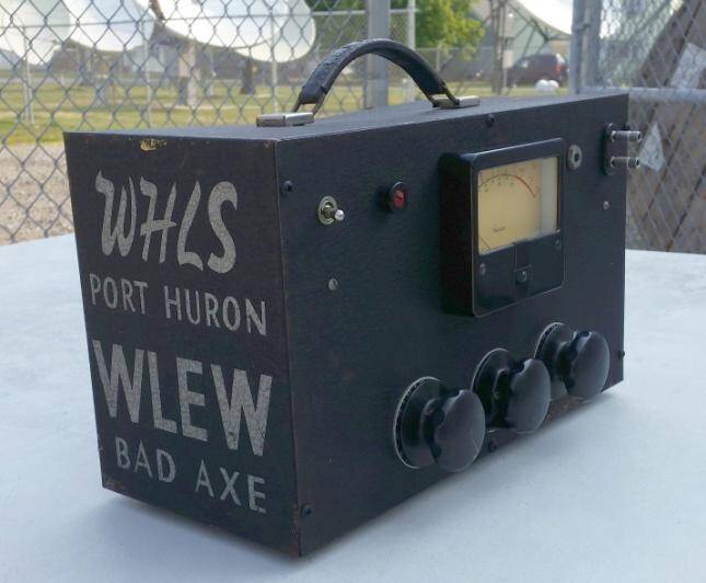
You can see why I called this the Bad Axe mixer
I have run into this problem myself, so I know there is no way to predict the best placement of the transformers. You must construct the circuit then try to correct the problem after you see what happens.
To the designer’s credit, he did use quality transformers, with decent magnetic shielding. But in an audio preamp circuit with lots of gain, hum finds its way in through unpredictable paths. Shielded tubes (6J7’s) were used, with shielded grid capacitors and shielded grid wires.
The 120 VAC wiring is shielded, as are the microphone input wires and the line output wires. Hum was definitely on the designer’s mind.
As a side note, the input transformer is a UTC LS-10X, and was considered a good quality transformer when this mixer was constructed. But now, among aficionados, it is considered to be among one of the best input transformers made, with NOS units fetching $500 plus on eBay!
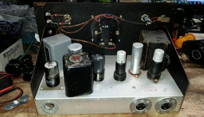
Rear view showing AC power socket, microphone inputs, tubes, transformers, etc.
A schematic of the mixer is included at the end of this article, for any who wish to examine the circuit details of this piece of vintage gear.
The following text describes my observations and records my comments:
LOOKING DEEPER INSIDE
The power supply uses a 6X5 rectifier – a tube notorious for burning up power transformers.
Originally, ‘6’-type rectifier tubes were created to reduce the cost of the power transformer. (Prior to the 6-type tubes, rectifiers used a separate 5 Volt winding on the power transformer for their filament voltage.)
A directly-heated rectifier tube was used, one that used the filament as the DC output element of the tube, the tube had no separate cathode. Type 80’s and 5U4’s are examples. Someone got the idea to add a cathode to the rectifier tube and change the filament voltage to 6 Volts.
This way, the rectifier filament can be powered by the same winding that powers the other 6 Volt filaments in the chassis.
The DC output of the rectifier is taken from the newly added cathode.
A POTENTIALLY DANGEROUS CIRCUIT
No separate 5 Volt winding is needed on the transformer which reduces the transformer cost. (Apparently, the transformer winding cost more than the cathode in the tube.)
Unfortunately, the new circuit topology places high voltage between the filament and the cathode. The purpose of the filament is to make the cathode hot – to create thermionic emission. Consequently, the cathode is a metal cylinder wrapped closely around the filament, but not touching it.
In most tubes, there are only a few Volts between filament and cathode, so their close proximity is not a problem. But when using the 6X5 as a rectifier, the cathode is at the rectified DC potential (often hundreds of Volts), and the filament is at the potential of the rest of the 6 Volt filaments in the chassis, which is usually ground.
Not surprisingly, when used like this, the 6X5 develops leakage between the cathode and filament, and if not caught in time, shorts out. This shorts B+ to the chassis, which, in unfused consumer electronics applications, often burns up the power transformer. So, in order to save a few pennies in parts costs, manufacturers produced thousands of ticking time bombs waiting to fail.
Luckily, even though the Bad Axe mixer uses a 6X5, it also uses a UTC HP-122 power transformer, which has two isolated 6 Volt filament windings. The designer of the mixer used one of the windings just to power the 6X5 filament, and returned the center tap of that winding to the 6X5 cathode. This way, there is no potential difference between the cathode and filament, so leakage and shorts do not matter.
CHECKING THE INPUTS
The microphone input connectors are old Cannon P-13’s, the predecessor to today’s XLR’s. They connect directly to the Daven attenuators on the front panel.
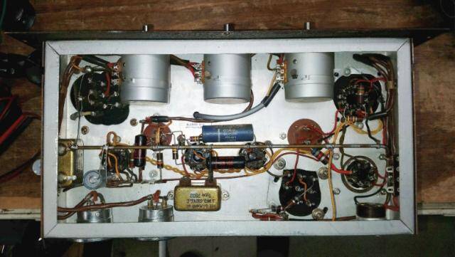
Inside the chassis. Notice the Daven pots
These Davens are 50 Ohms input, 100 Ohms output. I have no idea what type of microphone they thought would match into a 50 Ohm input. None that I know of will – and there is not enough gain in this preamp to work with ribbon microphones.
The 100 Ohm outputs of the Daven’s connect to opposite ends of the input transformer winding, which is strapped for 200 Ohms. This is a screwy setup, and I do not believe it works well (even if the Z’s were appropriately matched). The microphones are unbalanced, so they have no ability to reject common mode noise from external magnetic fields.
The 50 Ohm Z is so low that it will severely load any normal dynamic microphone, collapsing its output voltage, and probably causing loss of any low frequency response. Additionally, the circuit causes intermodulation by impressing a portion of the output voltage of one microphone onto the other microphone.
The effect is probably small, but it should not exist at all.
The specification on the LS-10X input transformer says its secondary winding is 50,000 Ohms – but it does not say if this is one winding or both.
Probably the only way to know for sure is to test it.
THE GAIN STRUCTURE
The 1st pentode, V1, a 6J7, probably has a gain of about 40 dB.
The input transformer probably has a voltage gain of about 15 (based on 200/50,000 Ohm Z’s), or about 23 dB. So, there is over 60 dB of gain before the main pot (V3). Note: Subsequent tests reveal there is about 63 dB of gain between the microphone input and the plate of V1. About 30 Volts peak-to-peak can be obtained at the plate of V1 before obvious distortion occurs in the waveform.
The 2nd pentode, V2, another 6J7, is set up just like V1, except negative feedback is applied to its cathode from the plate of V3. If I think of V2 and V3 like an op amp, then the gain is determined by the ratio of R5/R7, 270K/2.2K, or a little over 100, about 40 dB.
Note: Subsequent tests reveal that the gain from the grid of V2 to the plate of V3 is 40 dB, within 1 dB. The plate has approximately 30 Vpp sinewave on it when the VU meter reads 0 dB.
The output transformer is a Chicago Transformer B0-1. It has a 15 k Ohm input and is strapped for a 600 Ohm output. The turns ratio for this connection is 5, which is about 14 dB, which is a loss in this case. When the VU meter indicates 0 dB (sine), the output level at the Tip/Ring terminals about 7.5 dBu. When a 600 Ohm load is connected, the VU meter reading drops to about -3.5 dB, and the output level reads 3.9 dBm.
GETTING IT READY TO OPERATE
Over the period of a week, I reformed the electrolytic capacitors.
When I started, they were pulling excessive current and would heat up. Using an external current limited (15 mA) power supply, I started at 100 VDC and over a period of days I raised the voltage up to 350 Volts, keeping an eye on the voltages in the circuit so I could see what was pulling current. All the tubes were removed, so the filter capacitors should charge to their maximum voltage, without much voltage drop across the resistors in series with the B+ rail.
Each night, I removed the voltage and let the capacitors cool down. The next morning I would reapply yesterday’s final voltage…and verify that the capacitors would remain cool.
Then I would raise the voltage by about 50 Volts and let everything simmer for hours. The capacitors would warm up again by the end of the day. Eventually, I got up to 350 Volts, which I thought was high enough based on the power transformer specifications.
So, while the filter capacitors stopped drawing current, I was not sure about their capacitance.
After looking at the schematic, I thought I might be able to measure the capacitance in-circuit. I tried it, using a Triplett 5505 Capacitance Meter, and it worked. All the filter capacitors, except C3A measured OK. C3A was measuring low, about 11 uF instead of 20 uF. More about this in a moment.
The coupling capacitors, C4 and C9, were leaky. C10 was OK. I replaced C4 and C9 with some vintage Sprague Black Beauty’s from my junk box. R12 had changed in value; about 700 k Ohms instead of 470 k Ohms. I replaced it.
TURNING IT BACK ON
After replacing C4, C9, and R12, I put in the tubes and fired it up, applying a test signal to one of the microphone jacks, and got a deflection on the meter.
I do not know why R10 and R12 are there. Obviously, a DC bias is being applied to the filament string, but for what purpose? I do not believe this does anything to reduce hum.
I think a hum bucking pot would work better.
Eventually, I got to the point where I decided to hook the “Axe” to an external amp and listen to it. I connected it to an Anchor AN-1000X amplifier/speaker that I use in the shop for test purposes. I could hear residual hiss and hum from the circuitry as expected.
I turned up the main pot, and the noise increased somewhat as expected. Then at about 3 o’clock it started making a “fubb – fubb – fubb – fubb – fubb” sound! I recognized the sound immediately and had a pretty good idea of the cause. We used to call this sound “motorboating.”
SOLVING THE MOTORBOATING
The typical cause of motorboating is an open (or low value) power supply filter capacitor. Remember C3A? (it measured low in value.)
Motorboating is low frequency oscillation. By low frequency, I mean from sub-Hertz up to about 10 Hz. It is caused by interstage feedback being coupled through the power supply rail. The electrolytic filter capacitors on the power rails are supposed to prevent any signal modulation in a subsequent stage from coupling, via the power rails, back into a previous stage. C3A, being low in value, is undoubtedly allowing feedback to occur, resulting in the motorboating sound.
The simple fix is to parallel C3A with a new capacitor. I used a 47 uf @ 315 Volts. No more motorboating!
THE FINAL TEST
With that problem solved, I connected a microphone to the input using a 200 Ohm dynamic microphone to feed the 50 Ohm input, but it was perfectly adequate for the intended purpose.
Ready for action!
With only three knobs, the operation was quite simple. As I had expected, the low frequency response was not great.
But … the mixer worked! In the parlance of radio jocks, this Bad Axe is a Blast from the Past!
– – –
Michael D. Hahn is a staff engineer at WLIO, WOHL, WAMS, WPNM, & WFND Television in Lima, Ohio. You can contact him at: mhahn@wlio.com
– – –

Would you like to know when more articles like this are posted?
It only takes 30 seconds to sign up here for the one-time-a-week BDR Newsletter.