

Why Is 50 Ohms The Standard?
[October 2025] Many of the things technical people deal with have names or origins that are not necessarily clear or have been forgotten. This is one of a series answering the question: Why is it? In this installment, why is the coax impedance in broadcast usually 50 Ohms.
Although there are different impedances needed for different purposes and manifested by different sizes of coaxial cable, in broadcast, power transmission is almost always via 50 Ohm coax.
Why is it 50 Ohms?
What Do You Want To Carry?
When you look at this chart, developed a century ago, you can see where and how choices had to be made by the telephone engineers of the time.
One of the major concerns was the ability to carry a signal without Voltage breakdown.
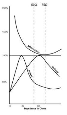 As can be seen from the bottom half of this chart, the best capacity for carrying Voltage efficiently is right around 60 Ohms.
This is near, according to the upper half, the point of least signal attenuation, which is around 75 Ohms.
So, why are the coaxial cables in broadcast usually 50 Ohms?
The Choice
As seen, the power handling capacity of coax cables is the highest at around 30 Ohms.
But the best impedance for Voltage transmission is about 77 Ohms. With no perfect impedance to match both parameters, a middle ground was both needed and desired.
For example, with broadcast transmitters running thousands (even megawatts) of power, it was deemed prudent to find a compromise of where the power and Voltage were as equally good as possible. Since power handling falls off rapidly above 30 or 40 Ohms, to balance Voltage, Power, and signal Attenuation, engineers of the day settled on 50 Ohms.
(When there is a relatively small signal, like receive antennas, 75 Ohms is almost perfect for passing on the Voltage of the signals. Hence, microwave and television cables usually run at 75 Ohms.
Cable Size
Next, manufacturers needed to design and build the cable to the right impedance – and in a manner that sections and ends can be reliably connected.
Calculations led to a ratio of inner conductor to outer conductor that results in the characteristic impedance for cables of varying sizes. For cable of 50 Ohms, for example, a center conductor of one-inch would require an outer conductor of 2.3 inches.
This can be scaled up as a ratio for the larger coax cables used in the highest power applications.
On the other hand, perhaps you may have heard of some cable and/or rigid line having an impedance of 51.5 Ohms. This came about because in the early days, the easiest materials available for the center conductors were common ¾-inch rods – and outer conductors made from 2-inch water pipes. (One can only recall that often transmission line is referred to as “plumbing.”)
It so happened that they ended up measuring as 51.5 Ohms.
[the_ad id=”3418″]
https://www.inovonicsbroadcast.com/
Getting Down to 50 Ohms
As precision manufacturing processes improved (or maybe water pipes changed a bit), 50 Ohms became adopted as the standard, although 51 or 51.5 Ohm cable an still be found, and occasionally 52, or even 53 Ohm products.
Another change was flexible coax made possible by materials like polyethylene. With its dielectric constant (2.3), filling a 77 Ohm air-filled cable with polyethylene resulted in an impedance of 51 Ohms. A slight change in dimensions and 50 Ohms became the common, default impedance for coax designed to carry higher powers.
And that is why your transmission coax cable is 50 Ohms.