

RF Radiation: Defining Polarity vs. Polarization

[March 2010] Sometimes not knowing the exact definitions can get in the way of understanding engineering terminology. Richard Fry discusses a pair of terms that often seem interchangeable, but are not. Taking the time to investigate leads to better understanding of what happens when the signal leaves your antenna.
When discussing electromagnetic radiation, the meaning applied to these two terms – Polarity and Polarization – often has been taken to be the same. However, let us take a quick look at them and see if we can clear up any confusion.
Defining the Terms
The Polarity of an electromagnetic wave is determined by its electric field vector, which reverses direction (polarity) every 180 degrees of the waveform — regardless of the polarization of the wave.
The Polarization of an electromagnetic wave is defined by the physical orientation of its electric field vector, regardless of the polarity of that field. For linear radiators such as a dipole and monopole, the direction of polarization is that of the physical orientation of the radiator.
So although these terms sound rather the same, they are not synonymous.
Visualizing the Terms
A good way to understand the relationship is with a visual aid. There is an applet on the Internet that is useful to visualize this. It can be found at:
http://www.amanogawa.com/archive/Polarization2/Polarization2-2.html
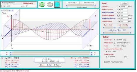
To see vertical polarization, first set the Ey field to zero, and start the animation (top center of the page). Then set the Ex field to zero and the Ey field to one to see horizontal polarization. The blue lines tending to fill in the AC waveform represent the electric field vectors of the radiated wave.
In this applet if the Ex and Ey fields are set to equal values (say at 1 each), and their phase relationship to -90 degrees using the slider below the Ex and Ey sliders in the Input Section of the applet, then the resulting EM field is perfect, right-hand circular polarization. The animation shows a net field vector of constant magnitude rotating through all polarization angles once per wavelength. The x and y fields can be deselected using the controls at the bottom center of the applet, which more clearly shows the c-pol field.
Also note that the perfect, c-pol field shown in the applet is the net field of two, linearly-polarized radiators when configured as described above.
– – –
Richard Fry spent 15 years as a Field Supervisor for RCA and nearly 20 years as an RF Applications Engineer at Harris Broadcast. He has been retired for 10 years, but still is actively sharing his experience on his website www.rfry.org, and by sharing in discussions on Internet mailing lists, such as on www.radiolists.net.