

Negative Towers are Just Numbers

[December 2015] Directional Antennas (DAs) can be a big mystery for some until they discover that with a little algebra, the basic concepts are fairly easy to understand. But when you mention negative towers, many folks just do not know how to grasp the concept – perhaps thinking of towers that go down into the ground.
Recently a discussion developed among some radio engineers on the Broadcast Mailing List (www.radiolists.net) trying to break through confusion about how negative towers work in AM directional antennas.
The problem is that it is easy to be confused by the difference between a tower with a negative phase and a “negative tower.” I would like to share a brief summation with very little math for those who are as math-challenged as I am.
The Basic DA
First, we should probably start by reviewing some very simplified DA basics.
In a DA, multiple towers are used to generate a directional pattern used mainly to protect other stations on the same (or adjacent) frequency or sometimes also to maximize signal to desired coverage areas. This is accomplished by sending more signal in some directions, less in others.
The transmitted shape, or pattern, is determined by the relative amount of RF fed to each tower, measured as a ratio of the current into that tower relative to the current in the “reference tower” (usually the highest-power tower, for maximum stability), and the relative timing of the RF signals to each tower, measured as a phase difference between the current in that tower relative to the reference tower, determine this pattern.
To accomplish this, transmitter power is split by power dividing and phase delay networks.
These are comprised of coils and capacitors in the phasor, then sent through coax cables to the various towers, where the signal goes through more networks in the Antenna Tuning Units to match the impedance of the coaxes to the towers’ base impedances and also contribute to the overall timing of the signals in the array, called the “phase budget.”
The large number of possibilities with two or more towers is beyond the scope of this article, but a quick visual demonstration is worth mentioning.
The following graphic is a basic illustration of two towers, non-directional in of themselves, spaced 90 degrees, fed equal currents 90 degrees apart.
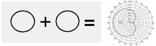
Two non-directional signals combine to make a cardiod pattern
The timing/phase of the signals in each tower can be leading (positive) or lagging (negative). These ratio and phase “parameters” are specified in the station’s FCC license. However, a tower with a negative phase is not a “negative tower.”
Why There Are Negative Towers
If we return to antenna basics for a moment, we recall an antenna is a structure that efficiently converts between RF power and electro-magnetic radiation (radio waves). At any frequency, a thin wire between 1/8 and 5/8-wavelength long (such as, in the AM band, towers between about 100 and 1000 feet) over a ground plane is a reasonably efficient antenna.
Now, here is something that is obvious, but often overlooked: Antennas are inherently twoway, converting RF to radio waves (transmitting) or vice versa (receiving) with equal efficiency. It is this two-way behavior that complicates the design of AM DA arrays.
Since each antenna in a DA is equally good at transmitting and receiving, some part of any signal transmitted by any given tower is received by all the other towers in the array. This effect is called mutual coupling.
The Negative Tower
In most arrays, the transmitter power flows from the phasor into all the towers in the array.
However, in some arrays, sufficient signals are coupled into a tower from the other nearby towers in the array to actually overcome the signal fed to that tower from the phasor, so that the net power flow is from the tower back into the phasor. It is in effect a net “receiving” antenna.
We call such a tower a “negative tower.”
Manipulating an Array
Whether any of the towers in an array are negative is determined by the height, spacing, and orientation of the towers in the array, as well as the current and phase parameters that create that array’s pattern.
If you change the parameters of an array (the current and/or phase), the pattern will obviously change. Interestingly, this action can affect whether a given tower has negative or positive power flow as well. Generally speaking, as you feed more power into a negative tower, at some point, the power fed to it will predominate over the power coupled into that tower from the other towers, and it will “flip positive.”
A negative tower also can have a positive or negative phase, as shown on the station’s antenna monitor. However, as we said before, negative phase has nothing to do with positive or negative power flow.
You also can develop a directional pattern by driving just one tower and grounding all the others; we call these towers “parasitic.”
An example of this type of antenna is the Yagi antenna. In a Yagi, only one element is driven, and all the others are grounded to the shaft of the antenna. However, although the concept is simple, we do not use parasitic arrays in AM DAs because such an array does not allow fine enough control of the pattern generated to meet the signal suppression levels needed to make the crowded AM band work.
Understanding Revers Flow
Here is a thought experiment that may help to clarify the idea a bit more: Imagine a 2-tower DA, with one tower fed from the transmitter and the other tower terminated in a resistive dummy load.
Obviously, the power flow at the terminated tower is negative, as power must flow from the tower to the load; there is no source of RF power to feed to that tower. Now, imagine that tower fed from a branch in the phasor with the power fed to it turned all the way down. Since there is no power dissipated in coils and capacitors (other than incidental losses), and there is no resistive load in the circuit, in this configuration, the second tower can be considered to be parasitic.
If, however, you raise the power fed to the second tower from zero (and the tower spacing is right to allow it), that tower will start to return power to the system, which will make it negative. If you continue to raise the power fed to that tower, at some point, the power fed to it will overcome the mutually coupled power back into it, and it will become a positive tower.
Finally, if you increase the power fed to that second tower to where it becomes the higherpower tower in the array, the other tower may itself go negative!
Tuning With a Negative Tower
As we see, it is easy to force a tower to go negative by terminating it into a dummy instead of allowing its power to be returned to the system.
This is sometimes done during an array tune-up to ensure that a tower is definitely negative with stable parameters. However, doing this literally throws away the power from the negative tower, which lowers the efficiency of the array, and so is seldom done as a permanent practice in an operating array.
In addition to being wasteful of energy (read: money), the FCC specifies minimum efficiencies for DA arrays, and while it is possible to sell them on using a dummy load to ensure a tower’s being negative or to improve the bandwidth of some arrays, it requires careful justifycation and many measurements to convince them that the array is indeed operating legally and properly.
Early phasor designs sometimes used various tricks to handle negative power flow returned to the power divider bus. However, there is no magic to it and, using modern design techniques, the branch for a negative tower is not wired or fed any differently from any other tower’s branch.
Diagnostics
You cannot tell if a tower is negative or positive just by reading the antenna monitor parameters. The only way to tell if a tower is negative is by using an Operating Impedance Bridge (OIB) or a directional Wattmeter such as a Bird 43 (yes, they make slugs for the AM band!).
If you connect a bridge at a J-plug for a tower in an array and the OIB wants to null “below zero” Ohms resistance, try reversing the leads – if it then shows a normal impedance, you have a negative tower.
With a Bird meter, which references everything to 50 Ohms, it is a little harder to diagnose, as most negative towers have impedances far from 50 +j0, so you will get high power levels with the slug pointed either way. But the direction of net power flow can be determined by which power reading is higher.
Close to Zero
It is even possible to have an array with a tower where the mutual coupling and the power fed to that tower balance almost completely, so that there is no or almost no net power flow into or out of that tower.
Note that such a tower does not have zero base current, but the current into the ATU will be almost zero and you will get a resistance reading of almost zero (with some reactance) on an OIB at that point, either way you connect the OIB leads.
If your array has a tower that wants to flip between positive and negative, you will not see any wild flips of phase on the monitor!
Unless you use a bridge as described above, you will not be able to tell which way the power flow is going from the antenna monitor.
More To It
All this is a very simplified recap of some of the concepts relating to negative towers.
If there is interest we could cover some of these aspects in greater detail, as well as further discussion on the construction and maintenance of DAs. And, it is worth mentioning there are excellent textbooks on DAs available. We will share some of this information in a future look at DAs.
– – –
Michael Patton is an industry veteran known for tackling hard-to-repair gear. He is President of Michael Patton and Associates in Baton Rouge, LA. You can contact him at: mike@michaelpatton.com