

Growing Tower Farms in M/SP Part 3 – Back On Track To The Sky

[September 2015] Looking back at how broadcasters built their sites to serve the community is more than just a casual look at history. Often, we can learn important lessons, not only how to get the job done, but also how to avoid mistakes. Steve Brown continues his look at the tower farms at Minneapolis-St. Paul.
For over a decade, signal improvement for the FM stations in Minneapolis-St. Paul was stymied by a collapsed tower and serious inter-modulation problems right in the heart of the cities which kept stations at about half-power.
There was no doubt the stations located on the IDS building in downtown Minneapolis were anxious to return to operation with the full 100 kW ERP at 1400 feet above average terrain (AAT) planned for the Telefarm site. After all, those stations had been “temporarily” moved to an elevation of only 823 feet – and forced by the FCC to reduce power to 50 kW ERP.
At least those stations were pretty much all in the same boat – and even at half power they were doing quite well. Proving that “content was King,” one station was able to achieve decent ratings from a site at only 253 feet AAT.
The Time to Upgrade Arrives
What really got things off the dime and moving again had everything to do with FCC Docket 80-90, which, among other things, created sub-C classes of FM licenses and required full Class C FM stations to mount antennae at least 984 feet above the average terrain (AAT).
By then, the cohesiveness of the IDS-located stations group had frayed. In 1979 several of the stations filed individual construction permit applications for the other tall tower site in Shoreview, which was then owned by United Television.
No master antenna was specified in their applications. And each one listed a different antenna height, make of antenna, and transmitter power output.
Clearly, you could not fit five separate FM antennas in a vertical aperture of several hundred feet, which was the available real estate on the United Tower.
A Master Antenna
Something had to give, and what resulted was a plan in 1989 for a master FM antenna.
In the process, all eligible stations in the Minneapolis/ St Paul market were invited to join the project. Finally, a partnership agreement between the five “IDS” stations, WCCO-FM (by then WLTE-FM) non-commercial KTIS-FM 98.5 MHz and KTCZ-FM 97.1 MHz was signed, which made for an eight-station group. Several other stations in the market elected not to join the project, but the political decision was made to plan for 10 stations to ultimately use the new facility.
The FCC was happy to grant the construction permits and get the mess off their plates, and the project that probably should have occurred in 1979 finally got underway.
I happened upon the manager of one of the FM stations at the NAB convention in Las Vegas in spring, 1989, just after the agreement was finalized. He asked if I thought the project could be operating by fall. “Sure,” I said. “Now we just have to decide in the fall of which year.” In fact, it took until the late summer of 1992 before the first RF hit the master antenna.
Don Your Dreamer Hats, Fellas!
An architectural firm with their in-house construction company was hired to do a scoping study with all stakeholders and then design and build the transmitter/combiner building.
Then a group of Chief Engineers from the original eight stations toured various vendor’s facilities, including the Harris antenna test range on the Mississippi River, the Harris and Broadcast Electronics transmitter manufacturing facilities in Quincy, IL, and the Continental Electronics transmitter plant in Dallas.
We also checked out the (then) new master antenna plant in St Louis, and got a lot of great ideas about how to lay out our new digs – and even a few ways not to lay things out. For example: do not locate sensitive electronics under the bathroom drain plumbing.
Back to the Drawing Board
We then sat down with the construction company to develop the building plans.
Due to space constraints at the site, a two-story building was roughed out, with transmitters on the top floor and the combining equipment, air handling and AC power distribution on the lower level, which is a walkout to the tower itself.
![]()
The building totals 14,000 total square feet on two levels, and each of the ten individual transmitter rooms measure about 23 feet by 18 feet.
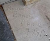
The concrete was poured in 1990.
Based on the original construction permit submitted to the FCC specified an 8-bay antenna, we planned for transmitter power outputs somewhere north of 30 kW per station.
Electrical, air handling and space requirements for the building took these numbers into account. The air handler was sized to handle the heat load generated by all stations operating at full power with just one of the two supplied A/C units, so that failure of one unit would not impede operations.
When the plans were finalized by the group, the design specification for electric power required enough juice for each station to be able to operate their main transmitter and an onsite backup transmitter into a dummy load at full power.
Not Quite Right Yet
All this may sound like overkill, but the building developed pretty much as we dreamed that it would, despite a last minute filing against the construction permit application by Minnesota Public Radio (they were not part of the project yet) which observed that the combined power output of potentially ten stations into an 8-bay panel antenna would put an objectionable amount of RF onto the ground in the vicinity of the tower.
This resulted in amending the CP application to specify a 12-bay panel antenna, which lowered the transmitter power requirements to less than 20 kW per station. At the same time, the original specifications for air handling, AC power and space remained the same. As it turned out, with the future addition of HD Radio, it turned out to be a fortuitous decision.
On a slightly humorous note, the station owners (the station managers, actually) demanded that each station have its own locked room for transmitting equipment. They got what they wanted concerning the locks, but never realized that all ten rooms used the same key!
Rethinking the Master Antenna
Meanwhile, we found it necessary to upgrade the master antenna somewhat.
We hired Dean Sargent, a nationally-known radio consulting engineer with lots of experience in combined FM transmitter plants to help develop specifications for the master antenna and combining equipment.
Specifications were drawn up and submitted to a group of manufacturers who we believed could deliver what we had asked for.
The winner was Alan Dick and Company of the United Kingdom, partly based on price but also considering their experience and design ideas.
 One of those unique ideas concerned RF power distribution in the antenna system itself.
The antenna is constructed as two 6-bay, 3-around panel of antennas stacked one on top of the other, each being fed by a 6-inch rigid transmission line coming up the tower from the combiner output.
In the course of power division to what turns out to be 72 individual antenna elements, a large 3 dB hybrid power divider is mounted at the center of each six bays.
In other designs (such as at Houston, TX) the fourth port of that hybrid was terminated in a large RF load, mounted on the tower. We heard that had been a problem.
Alan Dick’s engineers found a solution by adding a 7/8-inch run of Heliax from that port back down the tower and into the building, where it was connected to a Bird RF termination. This kept the RF load off the tower and, as a bonus, with the addition of a directional coupler and Wattmeter on the load, gave us a direct indication of the hybrid’s match at the antenna itself.
Let the Construction Begin!
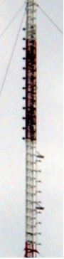
In addition to the design and build of the transmitter/combiner building, a structural analysis of the United tower showed that there was a lot of upgrading to be done.
Numerous horizontal and diagonal members of the tower needed beefing up or replacement, several levels of guy cables needed upsizing, and the tower legs themselves needed reinforcement. This led to another round of bidding for tower erection companies to do the reinforcement and then to hang the 12-bay panel antenna, the two runs of 6-inch transmission line and the 7/8-inch reject load lines.
A very large transmission line bridge with ice shield was planned (sturdy and wide enough to drive a Jeep across).
In addition, all eight original stations needed 950 MHz STL receive antennas hung at various levels on the tower and 7/8-inch Heliax feed lines. The STL work was sub-bed to a local tower crew because we felt the “big steel” guys doing the tower reinforcement operated under the assumption that “if a spud wrench won’t fit it, we don’t understand it.”
The “big” tower crew began the reinforcement project in the summer of 1991 but ran into problems with pre-heating the massive solid-rod tower legs at the base of the tower so they could weld on half-moon reinforcements up the first hundred feet of the tower.
Weather took its toll on their time, so they called it quits for the year in fall 1991, with no antenna or line yet in place.
Measure Once, Cut Twice
In the meantime, the building itself got completed in late summer, and we all started building out our transmitter rooms.
Seven new Continental 816R-3B transmitters got hooked up (KTIS-FM elected to go with a new Broadcast Electronics transmitter) racks were wired, and the combiner and antenna cleared customs in New York and hit the site that fall for final assembly.
Oops!
In the last few years you may remember the disastrous attempted landing of a rover on Mars, caused by a conversion error from metric to US measurements.
That issue bit us, too, with the combiner modules. “As built” building plans had been submitted to Alan Dick’s mechanical engineers but somehow the math conversion went awry and we were forced to move some large conduits from a support post to just barely clear the combiner modules.
In addition, there was some ‘runout’ on the combiner string: the faces of the output hybrids were not all exactly parallel.
So the string of modules went out of line about six inches from one end of the room to the other, which necessitated shimming things up on the hybrid faces to make things square.
Then our massive 9-inch patch-panel suffered shipping damage and needed to be rebuilt and reinforced in the field (the “big tower crew” did understand this and did a great job) just as winter set in with a whole season or so until tower reinforcement could continue.
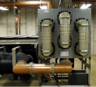
A Lot of Plumbing
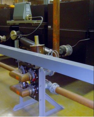
The original specified the power handling capability of each balanced bandpass-combiner module was 30 kW (before the antenna aperture changed) so the cavity size is 30 inches, rather than the usual 24 inches for the ultimate 20 kW power level.
The station modules are laid out in a string, with the highest frequency station at the beginning of the line. Each combiner module output hybrid is connected to the next module’s hybrid input.
The combiner module for each station is connected via RF patch-panels at both the input and output, so a faulty module can be bypassed for service.
These station modules are laid out in a string, with the highest frequency station at the beginning of the line with each combiner module output hybrid connected to the next module’s hybrid input.
This line begins with 3-inch rigid line and ends up 9 stations later with 9-inch EIA rigid line connected to a large 9-inch EIA patch-panel. That allows the combined power of all stations to be directed to either upper or lower 6-bay antenna if either half of the transmission line or antenna system fails.
By the way, the U-links in this patch-panel are made from aluminum, while all the other components are copper or brass. What was the reason for this? Weight!
Moving a 9-inch U-link on the patch-panel is still a two man job, and would probably require a hoist if copper was used.
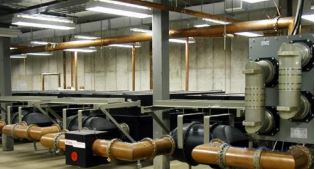
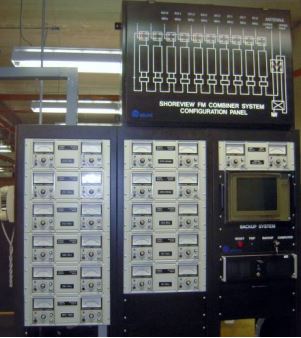
Keeping the Watts Moving Out
With all that power (eventually approaching 150 Kilowatts) being piped around the building and up to the antenna, we certainly did not want any part failure to cause a meltdown.
Therefore, we specified a monitor/protection system that would either cut back the power levels or interrupt carriers, depending on the type and severity of fault encountered.
One item of interest is one of the extra expenses the HP model 435 power meters added to this project. While a less costly solution would have been to use Bird Electronics ‘wattchers.”
The St Louis engineers had warned us about this, as they originally had used the Bird products to feed their monitor system – but found that inadvertently tapping on the Bird analog meter movement, or other vibration, would cause enough DC Voltage to be generated back into the monitor sample device to cause inaccurate readings or carrier shut downs.
The monitoring system specified MS DOS as an operating system with no mechanical disk drives for program storage. Unfortunately, Alan Dick sub-contracted this part of the project to someone in the US who apparently took their money and failed to deliver.
But at the last moment Alan Dick’s Ernie Mayberry stepped up, using Quickbasic software to interface with directional couplers and Hewlett Packard power meters and creating a system that operates just as intended to this day.
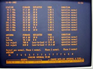
One feature of the system is to constantly log 76 different parameters, including all power meter readings (forward and reflected power for each station into its combiner module), forward and reflected power for each half of the antenna, the power level into each ground-mounted hybrid reject load.
In addition, the monitor protection system also checks the status of all the U links in the combiner input and output patch panels, nitrogen levels and AC line levels, and sends half power commands and carrier interruption commands to each station transmitter, as required.
Someone at Broadcast Electronics suggested the logs run in a first-in-last-out order, so if there is an alarm in the system you can go “back in time” to see what happened immediately before the alarm condition happened.
We Pause Now for the White Stuff
As we noted, Winter 1991 brought a pause in the project as weather basically shut down all work on the tower.
But that did not stop the behind-the-scenes-action. Over the winter Minnesota Public Radio purchased one of the stations in the Shoreview FM group (99.5 MHz) and changed format from CHR to non-commercial classical music.
With their entry into the group, plus the inclusion of WLTE-FM, the two companies that fought a 10-year battle with the “IDS stations” came to an end.
To quote Pogo from the cartoon strip, “We have met the enemy, and he is us.”
In our final installment, we learn about the invention of the Klippopotamus, the final installation and testing of the transmitters, combiner system, and antenna – and how they handled last minute glitches.
– – –
Steve Brown, aka the Radio Ranger, is now retired from WCCO-FM and enjoys backpacking in the Land of 10,000 Lakes. He has agreed to share his memories as part of a series that tells how FM stations in Minneapolis-St. Paul learned to improve their facilities and maximize coverage. You can email Steve at: radioranger@comcast.net