
An FM Mod Monitor is Not an Option!

[September 2014] Listening to a station on the car radio is not enough to know exactly what is happening. Proper test gear should be in every station – so you can tell exactly how good your signal is when it gets to your listeners.
In the very early days of radio broadcasting,there was very little in the way of instrumentation.
As a result, before crystal control became widespread stations could never be quite sure of their frequency until the Radio Inspector showed up and marked the correct setting on the transmitter’s face. Nor did stations have much idea of how efficiently their carriers were modulated,although you could always hear the “splatter” of overmodulation and could back-off the program level to avoid it.
An AM carrier may be modulated down to carrier cutoff and upward to twice (or a bit more of) its resting (unmodulated) value.
On the other hand, FM broadcasting theoretically has no modulation constraints, except that the carrier cannot be deviated down to a frequency of zero, and deviation must remain within the passband of the receiver. So to preserve bandwidth, and to make receiver design easy, a deviation standard was incorporated in the infancy of FM broadcasting: ±75 kHz deviation of the carrier.
This degree of deviation gives quite acceptable signal-to-noise performance on the commercial(VHF) FM broadcast band.
Measuring FM Deviation
A spectrum analyzer may be used to display“Bessel Nulls,” a term referring to the “null”(disappearance) of either the carrier or the first set of FM sidebands when the modulating frequency and the carrier deviation attain a certain mathematical relationship.
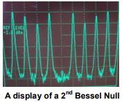
For example, using a spectrum analyzer and a steady tone set to 13.586 kHz, the carrier will null out at 100% modulation(75 kHz deviation).
This is a very accurate means of checking deviation, but useful only with test tones. A spectrum analyzer and Bessel nulls are worthless as indicators of carrier deviation by speech or music.
A modulation monitor, or “mod-monitor” like the Inovonics Model 531 is essential for metering an FM carrier deviated by a complex program waveform.
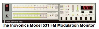
The mod-monitor may be accurately calibrated using Bessel-null functions, but must then present real-world program waveform deviation on some form of peak-responding display, either a mechanical meter or a bar graph readout.
Both of these display options require some means to hold the highest, fleeting modulation peak accurately so that it may be seen and acknowledged.
Measuring the FM Baseband
To be an accurate instrument, the total carrier modulation (total-mod) readout must exhibit a flat frequency response from (essentially) DC up to the 100 kHz maximum modulating frequency of FM broadcasting practice.
This DC-to-100 kHz spectrum is known as the FM baseband. While 100 kHz is well beyond the audible range, FM-multiplex stereo transmission uses frequencies to about 54 kHz. Also subcarrier transmission channels like RDS (the Radio Data System), SCA (music “storecasting,” readings for the blind, etc.) and various digital audio and data services also must be accounted for in any total-mod measurement.
The low-frequency end of the baseband turns out to be particularly important for accurate modulation measurement.
It is not just a matter of displaying the deviation of deep-bass frequencies in music; poor low frequency performance causes “tilt” in the recovered baseband waveform and sabotages the measurement of the entire baseband spectrum. Thus flat frequency response and flat phase response are crucial to accurate modulation measurement.
Why Have a Mod-Monitor
With 1960s and 1970s “deregulation” of US broadcast services, the requirement to have a working, type-accepted modulation monitor was lifted by the FCC. Other countries also may no longer require a station to have a modulation monitor on their premises.
Nevertheless, FM carrier deviation is regulated, worldwide, more strictly in some countries than in others.
To better understand the reason why a station should have a mod-monitor, consider an analogy between FM broadcasting and driving your car. There is a reason that while the first cars had no speedometers, today they all have them.
The reason is simple: you are bound by law to obey speed limits, and the violation of these limits can result in a fine or loss of your license. The modulation monitor is like the speedometer in your car. Whether your station has a modulation monitor or not, you are still required to keep your modulation within limits, or suffer the consequences.
Some FM exciters (or transmitters) are equipped with a rudimentary modulation indicator of some sort already built-in. But your on-air signal, which includes the transmission line and antenna, may not exactly reflect what is seen earlier in the transmission chain.
The Mod-Monitor And You
Compliance with Broadcasting Authority regulations should be of the utmost concern for the broadcaster.
FM overdeviation not only places the broadcaster in jeopardy of official reprimand and forfeitures, but makes him a disagreeable neighbor to other broadcasters in the marketplace as well. The same applies to subcarrier injection levels and generation of “incidental” AM noise components from a mistuned transmitter.
Despite denials and statements to the contrary, FM broadcasting remains engaged in the “Loudness Wars” that began in the 1960s. Makers of audio processing systems pay lip service to audio quality, often saying something to the effect that, “…our dedication to pristine audio quality does not come with a compromise in your station’s loudness…” or some-such qualifier.
Whether the premise is valid or not, “Burning a hole in the dial” is still a central issue with program directors and station management.
Beyond that, a mod-monitor is essential in identifying various issues in the RF chain, making them easier to remedy.
Selecting the Right Monitor
That is why, in addition to the all-important total-mod display, today’s practical mod-monitors incorporate additional utilities and features for maximum benefit to the FM broadcaster.
To help you choose a modulation monitor that will give you the information you need, here is a list of desirable mod-monitor features, along with how the Inovonics 531 FM mod-monitor meet these challenges.
1. The mod-monitor must be an off-air FM receiver of the very highest technical quality to fully recover the 100 kHz FM baseband.
This means its RF bandwidth necessarily must be far greater than a typical consumer radio. Ironically, this compromises the modmonitor’s performance as a radio; an off-air FM mod-monitor is not a good ‘DX’ (fringe area) receiver, and in most instances will not exhibit as good apparent sensitivity and selectivity as even an inexpensive car or portable FM radio.
The FM demodulation function must be exceedingly linear as well; that is, the recovered FM baseband must be an exact representation of carrier deviation.
The Inovonics 531 is a dual conversion receiver with linear-phase filtering at both the 10.7 MHz first IF frequency and 700 kHz second IF. The FM demodulator is a unique push-pull “pulse-counting” design with unparalleled linearity, inherently rejecting signals that are not part of the FM signal.
2. Any mod-monitor must of course provide stereo decoding with a precision greater than that of a consumer FM radio. The decoded left- and right-channel signals will be used to measure stereo separation and crosstalk across the audible range.
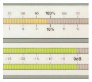
The stereo decoder of the Inovonics 531 is a phase-locked-loop (PLL) comprising multiple “building block” components. It is not a consumer-radio chip with its inherent limitations. Left- and right-channel audio programs are displayed on separate quasi-peakresponding meters, and follow either the 75- microsecond or 50-microsecond de-emphasis characteristic.
3. A top-notch mod-monitor will selectively show the injection levels of popular FM subcarrier services. This is important for setting RDS and other subcarriers to the levels they need to maintain for reliable operation.
The Inovonics 531 displays the peak injecttion level of subcarriers at 57 kHz (RDS), 67 kHz and 92 kHz (audio SCA), the residual level of the 38 kHz “suppressed” stereo subcarrier, and the injection of the 19 kHz stereo pilot.
4. A very useful mod-monitor feature is the display of incidental, synchronous amplitude locations to alert personnel to the various faults.
An Obvious Choice
Of course I am biased, but the Inovonics 531 mod-monitor has a proven track record as a “workhorse” FM modulation monitor.
The 531 is designed and built in the US using standard, commonly-available component parts, it has become a standard within the industry, and has been specified by broadcast groups and regulatory authorities alike for many installations in the US as well as overseas.
Now that you know why a modulation monitor is so essential to your operations, we invite you to take a look at the Model 531 and see why may well be your obvious choice, too.
– – –
Jim Wood is a co-founder of Inovonics, located in Felton, CA. He can be reached by email at: jim@inovon.com