

Adapting the FIM-21 Field Strength Meter For Operation with “AA” or “D” Batteries

[July 2012] For Jim Pollock, the battery compartment in one particular FIM-21 became a source of intermittent power trouble. Jim shares his solution: a modification that has proven to be useful in his work.
The FIM-21 is a highly accurate, easy to use Field Intensity Meter. It has been an industry workhorse for decades.
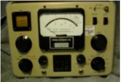
Potomac Instruments FIM-21
Most of the time.
An Annoying Issue
During a field measurement trip, a friend told me about how his FIM-21 was giving him fits with sudden outages. The unit would just go dead all of a sudden.
Shaking the instrument usually brought it back to life, but then my friend found he had to recalibrate. He had tried stuffing folded paper to get the D cell batteries to align better and keep going, but the outages still occurred.
More recently, I experienced a similar outage problem while on the road. It is a heart breaker when it causes everything to stop while you try to deal with it. My friend and I both tried the usual stuff like spinning the batteries, cleaning the contacts with a pink-pearl eraser, etc.
The Problem Identified
The problem was finally traced to a spring loaded pressure plate which would bind on occasion and not provide adequate or balanced contact pressure on the D cell battery stack.
The battery stack contact pressure spring mechanism is not accessible unless the battery compartment is separated from the instrument’s enclosure. This meant drilling out the rivets that secured the battery compartment box which also provides a tight RF shield.
Normal, proper repair of the D cell compartment could be rendered only if the instrument was sent back to the “shop.”
Because the FIM was needed in two back-to-back field assignments, and the schedules were very tight, sending it to company for repairs was not an option. While a formidable task for basic hand tools, it was deemed a better solution to work around the problem.
A plan was devised to modify the FIM-21 to run on a pack of AA batteries since AA batteries are more available and they are often on sale at substantial discounts in lots of 20, 30 or more. At the same time, we wanted to be sure to preserve normal D cell operation.
Field Modification
The modification we decided to implement on an FIM-21 to utilize AA batteries seemed to include the following criteria:
- Innocuous; The value and utility of the FIM shall not be diminished by any modification. Instrument accuracy shall not be affected.
- Transparent; The modification is an underlay of the present “D” cell battery box. Thus you can revert to using “D” cells at any time.
- Practical; The modification can be done easily by anyone who is proficient in the use of basic hand tools and soldering stations.
- Fool Proof; Safeguards shall be included to prevent damage due to accidental polarity reversals (i.e., a blocking diode).
- Partitioned: The modification only involves the rear of the FIM enclosure. The front panel of the FIM enclosure with all electronics attached there-to, is to be set aside in a safe place during the work.
- Reliable; The modification works 100% of the time.
Specifications
The first task was to ensure AA batteries could be used to substitute for the D Cells normally used in the FIM-21.
We can determine the system power requirements by referring to the manual. Taking our own measurements would verify the data and provide assurance the modification would work as expected.
Often, capacity is specified in terms of ampere-hours. However, ampere-hour capacity often decreases at the upper current levels of the curves. Also, batteries used intermittently will achieve longer cumulative running times under the same load conditions compared to those used continuously.
In this case, we measured the following operating parameters:
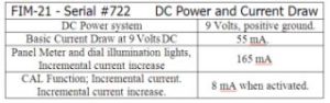
Battery Life
To make sure AA batteries would stand up to the FIM-21’s power needs, we needed to start by calculating the expected battery life from a fresh set of AAs.
The current drawn from the battery and a given terminal voltage are used with the battery’s capacity curves to determine the run time limit as to when the battery stack should be replaced.
The stop limit for the FIM-21 is when the stack terminal voltage drops to approximately 7 Volts. This is approximately to 1.16 Volts per battery in a stack of six AA cells. According to information from Duracell for AA cells with the Part #MN1500, the value of 55 mA on the current discharge axis intersects the 1.16 Volt curve at the point of approximately 30 service hours.
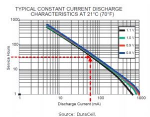
The battery life curve for a DuraCell AA battery
To convert that into a useful measure of battery life for field measurements it was assumed that each measurement requires 60 seconds if the FIM is set on a fixed frequency, including calibration steps.
Therefore one hour of battery use equates to approximately 60 measurements.
As mentioned, the useful life of the batteries ends when less than 7 Volts is presented to the FIM-21 circuitry. This equates to the “5” on the outer scale when in the BATT mode.

Typical reading with a new pack of AA batteries
Although the illumination lamps are included for night readings, they offer an excellent stress test for the battery.
For example, if the meter reading dips below “5” on the upper meter scale in the “BATT” mode with the lamps on, then the batteries should be replaced immediately.
With this information, we can quickly factor the data up and get a good indication of an expected operational life.
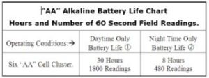
1 Meter and Frequency Dial Lamps not used during measurements: The Meter and Frequency Dial Lamps are turned on, in “BATT” mode, for battery tests. A reading below “5” means that replacement is necessary.
2 Battery Life if Meter and Frequency Dial Lamps are in use during measurement: Battery reading below “5” in the BATT mode means that replacement is necessary.
* In both cases, the volume was operated at approximately one-half of the maximum volume.
We considered additional tests with rechargeable batteries, but since those discharge even when not being used, it was felt the relatively cheap price of AAs made them a better choice.
With all this information in mind, it is clear that AA batteries can make a useful replacement for the D cells.
It remains now to find a non-destructive way to insert them into the FIM-21 case.
What It Will Take
Before we discuss the modifications, it would be a good idea to take a look at the power supply section of the FIM-21.
You will find that on the next page.
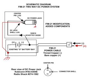
Some notes on this schematics:
- The chassis ground in an FIM-21 is positive (+).
- The male pin at the end of the power cable is (+); the female pin is (-).
- The power cable is, apparently, #16 zip wire with a clear insulation which allows the color of the wires to be viewed.
- The forward voltage drop of a Schottky barrier rectifier is substantially less than that of a standard junction rectifier.
Prepping For the Modification
Now it is time to get ready to do the work, it is good to assemble all the parts and tools.
Most all these parts and tools should be available at your local parts shop.
Tools Used For the Modification
- Eye protection; i.e., Safety Glasses.
- Volt-Ohm-Meter.
- Spring loaded center punch.
- Copper de-soldering braid.
- Cordless Variable Speed, Electric Drill with an assortment of drill bits.
- #30 for the 4-40 screw clearance hole.
- #50 for pilot holes.
- Progressive sizes from 1/16” to 5/16” for drilling DC Power Jack mounting hole.
- Dial Calipers (for making precise measurements.)
- A Soldering Station; such as a Weller Model WESD51.
- Rosin core solder.
- 5/64” Allen wrench (this is the next size up from 1/16”).
- 1/8” Allen wrench.
- #1 blade screw driver.
- #2 Phillips head screwdriver.
- Butane lighter or heat gun (preferred) for setting heat shrink tubing.
Materials, Parts.
- 8 cell holder for “AA” Batteries,
- 2 “AA” Dummy cells.
- 1 inch; 3/16” heat shrink tubing, Black
- 1 inch; 1/8” heat shrink tubing, Black
- 1 inch; 1/4” heat shrink tubing, Red.
- 1 inch; 1/8” heat shrink tubing, Red.
- 3/8 x 4-40 brass screw. (one each).
- 4-40 Brass nuts. (two each).
- #4 bronze split lock washer, (two each)
- #4 brass flat washer (one each).
- 5/16” brass flat washer (one each)
- 2.1mm x 5.5mm Coaxial DC Power Jack; Radio Shack #274-1582. Kobiconn #163-4304-E.
- 2.1mm x 5.5mm Coaxial DC Power Plug; Radio Shack #274-1569.
(Note: As a matter of personal preference, please consider the 2.1 x 5.5 mm male plug made by Steren. The Steren plug has an extended handle which includes a flex and strain relief. Also, there is more room for heat shrink tubing in the Steren plug.) - 1N5818 Schottky barrier rectifier diode.
The Operating Room is Ready
The first thing to do, as mentioned earlier, is to disassemble the FIM-21 back section from the front. Put the front section aside in a protected environment so that nothing falls into it, neither dust nor particles from the modification.
Here is the FIM-21 Battery Bay Drill Diagram.
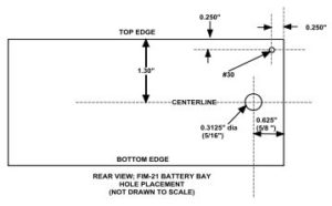
From a safety viewpoint, it is better to make several passes at drilling a large hole by starting with a 1/16” drill bit, and making the hole progressively larger with sequentially larger drill bits. The sheet metal work-piece will have a lesser tendency to buckle or be grabbed and spun out of your hands by the drill.
Notes The 5/16” hole shall be located on the centerline. This will provide clearance for the “D” batteries if the DC Power Jack is not used.
Positioning on the center-line is not especially critical.
As we put the parts together, here are a few detailed pictures to show how the pieces fit.
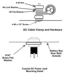
The importance of locating the DC Jack at the centerline is shown in the following clearance diagram. Without this clearance gap; the modification loses its transparency.
![]()
The clearance is attained by adding a 5/16” brass washer at the outside in order to decrease the connector shell height above the interior floor of the battery bay.
The DC Power Jack is located on the lateral center line of the Battery Bay. The center pin on the DC Power Jack is (-)
When done, it will look like this:
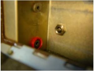
The DC Power Jack shown on the back plane
The contact surrounded by a red guide cup is the (+) contact for the D-Cell Batteries and the contact above is the (-) contact, which is isolated from the chassis.
Reviewing the Work
If you have followed the drilling diagram and installed the jacks and cable clamps as noted, your FIM-21 back shell should look like this:
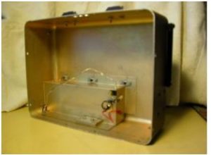
The internal side of the battery compartment
The next picture is a close up of the items that have been added as a part of this modification project.
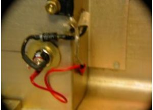
Post-mod view of the rear enclosure shell
The power cable anchor and strain relief was relocated to the upper left corner of the battery bay. This change resulted in about two more inches of cable run.
The 1N5817 Schottky barrier diode, with its leads encased in heat shrink tubing, is barely visible above the DC Jack.
The redundant RED ground wire connects the DC Power jack shell to the chassis ground. Although the shell is mounted to the chassis, the redundant red wire assures continuity in case the retaining nut on the DC jack work loose.
The existing “D” battery lugs are riveted, and should be approached with caution to prevent damage. Heat shrink tubing on those lugs were replaced after the Schottky rectifier and ground wire were soldered in.
Each lug was carefully de-soldered with fluxed braid, but the existing wires were not removed.
The wiring of each lug was completed one at a time in an orderly sequence to prevent confusion and wiring errors.
The AA Battery Pack
All that remains is to put the AA batteries into the holder and insert them into the FIM-21 battery compartment.
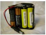
Although the battery holders are designed for eight cells, two “Dummy” cells are used in each battery holder.
Why not use all eight available battery slots? Primarily to avoid shortening the life of the meter lamps by exceeding their rating.
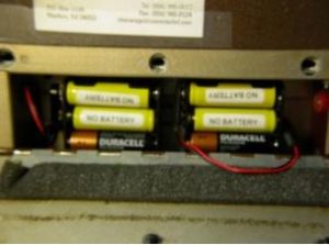
Compartment with two, 6-cell, battery packs.
The cell pack on the left is on-line. The cell pack on the right is a spare which is at the ready for an instant exchange.
Tips and Hints
In the course of doing this project, I made a list of tips and some hints that might make this project easier for you.
Use a variable speed drill:
Avoid using a single speed drill. You will be much more accurate with a variable speed drill because of better manual control over start-up torque.
Pre-Modification check:
Verify the voltage polarity at the end of the DC Power cable with the “D” batteries installed in the battery bay. Make a sketch of the connector, and mark the sketch as to which pins are (+) and (-).
Post-Modification check:
- Verify the absence of polarity reversals.
- Install the “AA” Battery pack, and plug it into the DC jack.
- With the positive lead of the Volt-Ohm-Meter at chassis ground;
- Measure the voltage at the old (-) “D” battery contact pad on the upper left end of Battery bay.
- The meter should indicate about +9 volts.
Heat-shrink tubing is your friend.
Cover all solder lug and connector pin solder joints with heat shrink tubing as a strain reliever against vibration and mechanical tension.
Adopt a wiring color code.
Adopt a scheme that sorts out the direction of current flow.
Use Black insulated stranded wire and Black heat-shrink tubing for the negative (-) power side of the batteries.
Use Red insulated stranded wire and Red heat shrink-tubing for the positive (+) power side of the batteries.
Clean your holes.
Remove all drill turning chards and filings from the project site. De-burr the exit wounds of all drilled holes, and dispose of the metal filings. Otherwise this junk will find its way to become lodged between the plates of the air-variable capacitors. Do not use sandpaper – it will damage the Iradite conductive plating.
A handheld drill bit, which is substantially larger that the hole being dressed, can be used as a de-burring tool. A sharp pen-knife is another option.
Do Not Use Wall Warts!
Yet another warning. There are wall warts out there with a (-) center pin but most wall warts are wired for a (+) center pin. The blocking diode will prevent catastrophe, but to prevent issues if someone else uses your FIM-21, just avoid using wall warts.
– – –
James W. Pollock, P.E., C.B.T., C.B.N.T, is a consulting engineer based in Mt. Laurel, NJ. He can be contacted at: jim@jimpollock.net