

Testing Your Solid-State Rectifiers

[June 2014] Even as everything goes digital, the solid-state rectifier is still the primary building block for the power sources which make virtually all things go. Since every decent technician must have a good working familiarity with them, Gary Minker shows how to test and diagnose some of the common problems that can cause problems in your power supplies.
We live in a world where direct current reigns supreme.
To provide all that DC, power supply designs have evolved from brute force to modern rectification of the alternating current from the primary line supply gives a new meaning to the old term “constant voltage.”
Experienced technicians might remember their experiences with the forerunners of today’s silicon rectifier devices. Glowing in the dark, hot cathode tube and mercury vapor type devices introduced many to the world of direct current.
That technology afforded no “instant on” use. Indeed, it required lengthy warm-up times and undesirable (by today’s standards) operating characteristics to insure the proper operation of filament-driven rectifiers. Vibration or extremes of cold wreaked havoc on these devices among other constraints.
And any failure to follow the stated proper care and feeding of these devices no doubt meant an early failure, X-ray radiation, and replacement. Though still in limited use today, these early devices led the way to Selenium, Germanium, and finally the modern p/n junction and silicon-controlled rectifiers of today.
Test or Replace?
Consumer level products usually must yield to the economic pressures which dictate a throw-away style for replacement parts or even entire assemblies – repair is warranted only under the most unusual of circumstances.
While typically generic in specification, that is why silicon devices should be readily kept on hand for just such situations.
Of course, test bed time and diagnostic interpretation can be costly. Testing a suspect defective silicon for subsequent reinstallation or replacement usually falls under economic guidelines:
Timely decisions are made to continue testing or to simply “shotgun” the circuit with on-hand parts – although this decision is often influenced by the lack of sufficient parts to effectively “shotgun” the circuit.
This leads back to the pressing need to know how to efficiently – and most importantly – accurately diagnose a problem and its suspect defective devices, so that only the defective devices may be replaced with parts on hand.
In those applications where effective, accurate testing and diagnosis of the suspect components is required, there are other avenues of support. This includes professional and industrial grades of technology which mandate the sophisticated testing and repair due equipment of this caliber.
Eventually you will find yourself troubleshooting a piece of gear where you will need to know if the solid-state rectifiers are working correctly. Testing does not have to be rocket science; some basic equipment and common sense is all you need for most situations.
Indeed, as we shall see, while digital and analog meters are helpful, the old Lissajou trace still reigns supreme.
Pass or Fail?
Once the big box has blown the breaker off the wall for the Nth time, and the situation has become painfully obvious that the power supply problem must be effectively diagnosed.
The suspect silicons may be examined more easily if, at your earlier convenience, you have developed a set of look up charts, tables and Lissajou traces outlining the assorted devices incorporated into your equipment. This preventive maintenance exercise will give the technician a greater level of understanding of the normal operation of a device while allowing him to remove the suspect components and examine them based on these previously developed charts and photographs of the curve traces of the junctions within the device.
Reference Notes
Such reference charts or graphs should contain these parameters:
- Forward breakdown voltage.
- Expected normal milliampere flow at a given forward voltage (both above breakdown and below breakdown.
- Expected normal reverse bias milliamperage (below peak inverse voltage – PIV) yes, some diode stacks do have a resistive reverse flow.
- Reference Lissajous traces of junction activity at repeatable parameters (curve traces).
- Forward bias resistance or diode function test readings (ie, the Ohms/voltage drop).
- Reverse bias resistance readings (in Ohms – and yes, they are different).
- Capacitance measurements of device in forward and reverse bias.
It is important to remember that in-circuit testing of these devices is seldom reliable. Each class of device will respond differently to the graph and chart references.
The reason it is hard to get a valid or reliable reading if performed in-circuit is that many of these tests are “bias polarity” sensitive. While all diodes will respond to forward break-down test, some require special test jigs or higher voltage equipment. All diodes will exhibit predictable forward milliamperage flow at a given voltage, though some require test equipment capable of generating hundreds of Volts.
Each device will exhibit a predictable milliamperage flow in a reverse bias condition as long as the PIV is not exceeded. Note, too, zener or regulating silicon devices will not conform to the usual p/n junction testing rules.
Setting Up a Display
An optical (Lissajou) comparison of a junction’s activity often is the best diagnostic aid. The behavioral characteristics of a junction are easily and completely observed at varying voltage and amperage ranges when displayed on a CRT or LCD screen.
The subtle curve changes that may be glaringly obvious when displayed as an optical anomaly on an otherwise linear curve would probably go undetected when tested by any other analog means, such as an Ohm meter.
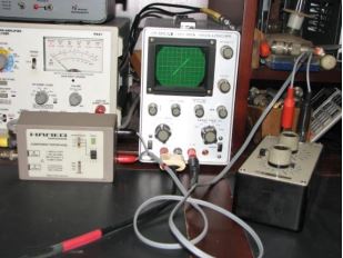
A typical setup to test rectifiers
Zener devices are best tested via a curve trace-Lissajous unit and a suitable capacitor leakage test meter. The “diode test” function incorporated into many of the more modern digital meters will give a very accurate indication of the actual voltage conduction point of the junction under test for non-stacked units. This reading should be repeatable from device to device. In the case where a device under test deviates from this norm, a virtual red flag should wave vigorously.
With the incredibly high resistance readings possible with modern test equipment, this category pays particular attention to resistor-equalized, stacked device arrays. In most cases the reverse bias milliamperage and Ohmic readings will give the proper lookup chart data for these devices under test.
In a resistor-equalized case the indication of an open equalizing resistor will warn you of an almost immediate subsequent failure in the stack, and in the same diode position.
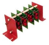
A stacked diode assembly
Capacitance measurements will provide reliable and repeatable references in resistively unequalized high voltage devices in both bias polarities. These forward and reverse readings would be distinctly different.
Equally important to these look-up charts and tests is the visual inspection. All too often the engrossed technician will overlook the obvious when trying to examine a defective circuit or diode stack.
Under test conditions, depending on the type of capacitance tester, lower voltage devices will display a shorted condition indication when tested in one or the other bias mode. Only one repeatable capacitance reading will be provided.
As you go along, you will see each type of diode device will have an anatomy of its own which can be easily used to identify good and bad components.
Look-Up Charts and Graphs

Crash Cart
Time is of the essence may be an old adage but in the realm of efficient diagnosis it is all too true.
Nothing is slower than having to dig to find each piece of test equipment. Even if it is just sitting on the shelf, having to hook it up, power it up, and integrate it with any other support device just all takes time that you may not have to spare.
In an active service environment where the broken equipment does not always come to you, you must more importantly go to the equipment. Enter: the Crash Cart.
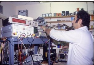
The Crash Cart
This tremendously impressive display of gauche industrial blinking lights and numbers will typically save 45 minutes of setup time. And the integration of the required test instruments within the framework of the cart makes unusual and off the wall testing possible with very little reconfiguration.
A good example is to be able to easily test an SCR though disconnected and still mounted, while simultaneously watching the gate voltage on the scope and or digital meter. Not to mention you are monitoring the gate in reference to either anode or cathode. The apparent benefit of the well equipped crash cart is only too obvious.
For your review, the cart pictured, tailored to a combined audio and R.F. environment, is equipped with the following pieces of equipment and more:
- Dual-trace scope.
- Scope for curve trace function.
- Digital meter.
- Spectrum analyzer (audio).
- Mono/stereo multiple input RMS reading voltmeter/Watt meter (audio).
- Frequency counter.
- Audio frequency generator / digital dBm meter.
- Power line disturbance monitor
- Audio distortion analyzer
- Soldering station / solder sucker.
- SCR test adaptor
- Capacitor/inductor test meter.
- Arc gap tester.
- Grid dip meter.
- Headphones.
- Vise.
- Impedance meter.
- Test leads (customized for ease of test).
- Other instruments as needed.
Adaptivity
In the test environment, adaptivity is the key to intuitive diagnostics. Before the age of measurement isolation systems, (voltage, current, pressure, infrared thermal sensing and, imaging) the test environment was predominantly referenced to ground. Those test fixtures and meters would only read a parameter referenced to ground.
Many of today’s technicians have been engrained that this early basis for test is the most proper avenue of diagnosis. While this is very true in some respects, the adaptivity of today’s new test instruments give a new twist to measurement techniques.
While a good ground is important for safety, an isolated input and battery powered test meters allow the technician the freedom to measure or view a test point not referenced to ground but from one gated or stacked level to another, as long as the voltages are within reason.
Silicon controlled rectifiers and industrial Triacs are the best example of junction devices that are triggered or “fire” in more than one mode. Isolated measurements of the elevated test points will often give the key to a trouble spot in these circuits. You can actually measure across the device and determine the voltage drop and other characteristics as compared to other brother devices.
Variations coming from circumstance motivated tests would include directly reading the voltage drop across an active rectifier element, or hanging a battery powered, insulated scope across the same rectifier or other control silicon device, and actually observing the junction operate.
Adaptive testing with the proper and safe test equipment will save much diagnostic time, especially where test equipment resources may be limited.
Now that you know the basics about what it takes to get ready to trouble shoot solid-state rectifiers, it is time to put all that to use. We will show you how in our next article, coming along shortly.
– – –
Gary Minker is the president of Radio Works RF Consulting, in Lake Worth, Florida. He can be contacted at gary@radioworksrfconsulting.com or (561) 969-9245